This does not align with any of the exam topics in the CCNA however, this is a fundamental knowledge that even many professional network engineers do not understand properly. This covers how two device on the same network.
Introduction to LANs
A LAN is a Local Area Network. It is essentially a small geographical location where endpoints such as a PC, Smartphone, Server etc can communicate with each other. These hosts are very close by and connected by a Switch or via Wireless Medium. In today's networks a LAN is comprised of Ethernet LANs. Ethernet is a Layer 2 technology.
When computer networks were first starting to be developed back in the 1970s/80s, there were many companies attempting to create a computer network. Eventually Ethernet was developed as a method of communication between devices in the same LAN, and switches were also created. A lot of companies adopted this ethernet methodology for their LAN and implemented it.
At this time, they were not aware of TCP/IP was also being created. TCP/IP was a different idea, it was to connect two or more networks together. So TCP/IP includes the Application, Transport, Network, Data-Link and Physical Layers. However, Ethernet was later added as part of the Data-Link technology.
One thing critical to understand as we will see is that computers and network devices and pretty much any electrical computer will only understand 1's and 0s. They do not understand words like we do. In the backend its encoded and decoded into 1's and 0's.
Every device that communicates on the internet or any type of network communication will have a NIC card and this NIC card will without a doubt be programmed with TCP/IP code inside of it. Within the NIC it may have 1 or 2 or more RJ45 ports. RJ45 ports are used to insert Ethernet cabling inside of them. Because of this, when data is sent over the wire as 1/0s we must follow ethernet standards.
Every LAN will have its own network address. Whether its in the 10.0.0.0/8, 172.16.0.0/12 or 192.168.0.0/16 private ranges does not matter, as long as a LAN has devices which are assigned IP addresses within one of these private ranges, they should be able to communicate IF they are in the same network. For example, if we want 192.168.10.10/24 to communicate with 192.168.10.20/24, they should be able to communicate and we will discuss how. However, if we want 192.168.10.10/24 to communicate with 192.168.20.10/24 they are both in separate networks. By default the communication will fail unless we introduce a Layer 3 device which we will discuss.
Same LAN Communication
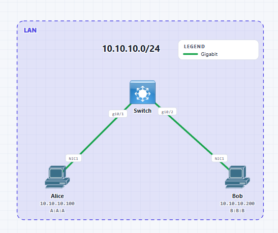
Here is out simple LAN topology. Here we have Alice and Bob connected to the same switch. They have both been assigned an IP address either statically or via DHCP (outside of this scope). Both of them have the full TCP/IP stack implemented on their respective gi0/0 NIC cards.
We will not be covering Ping in detail. This will be covered later. But what Ping is in essence is a network utility tool which generates messages Network layer not at the Application layer. It allows for testing if another IP address is reachable or not. Since it is at the network layer, it means there is no underlying application or transport mechanism involved.
In our example Alice is pining bob at his IP address 10.10.10.200. What we need to understand is ping allows for request packets and response packets via the switch medium we currently have. So what actually happens when we do this ping?
This is simple enough to understand, the ICMP/Ping is our "data" in this case and the destination IP address is for Bob at 10.10.10.200 and the request is coming from Alice from 10.10.10.100. However, for this to actually be sent on the wire, the wire does not understand IP addresses. It understands Ethernet. This means all of the above will have to be encapsulated inside of a L2 Ethernet header as we see below:
Here we can see that the IP Packet has been encapsulated inside of this L2 Ethernet Frame. We can now just refer to this as a "Data Packet". When packets are encapsulated at Layer 2, we call this a Frame.
We now know that the source is Alice's MAC Address because she is the one who wants to send this message, however we have absolutely no idea on what is Bob's MAC Address? And if we don't know his MAC Address then she (as of now) can never send this frame onto the wire. What is the solution to this? ARP is the solution.
Address Resolution Protocol
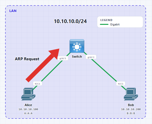
The switch does not have any IP address because it is a Layer 2 switch and does not understand the IP Packets only Layer 2 Frames. However before it sends the frame on the Ethernet Wire, it first checks if the destination is in the same subnet or not. In this case it is in the same LAN/Subnet.
The physical NIC card of Alice is an RJ45 port which is Ethernet and if we want to send this IP packet over the wire it needs to be encapsulated into the L2 Frame. And what does an L2 frame require? It requires a Source and Destination MAC address.
Alice know's her MAC address but she does not know bob. This means we are currently left with the below:
This currently as is cannot be sent onto the wire. It is impossible as we need the destination MAC address. So the host Alice will save this in her memory and will use ARP to get the MAC address of Bob.
ARP stands for Address resolution protocol and is the key protocol that runs at Layer 2. It maps a known Layer 3 IP address into a MAC address. An ARP message includes both an ARP request and an ARP reply.
ARP Request
Here is the ARP Request Data. It includes the following:
- Sender MAC - This is Alice's MAC address and this is known as she is the one generating this ARP request.
- Sender IP- This is Alice's IP address and this is known as she is the one generating this ARP request.
- Target MAC - We don't know the MAC Address of the destination that is the whole intent and purpose of ARP. We are trying to find out what this is.
- Target IP - We know this because of Ping. Alice Initiated the ping she typed it out so she knows what Bob's logical address is. In reality outside of Ping, the Application Layer would know the IP of the destination.
This is great, however we have run into another issue. How can this ARP packet go onto the wire if we don't know the destination MAC address? Remember, that everything that goes on the wire of an ethernet segment needs to have a source and destination MAC address and ARP is no different. So what happens?
Here we have encapsulated the ARP into a Layer 2 Ethernet Frame. The destination MAC address we have set here is all FFFF:FFFF:FFFF's. This is a special address known as the Layer 2 Broadcast Address.
A Broadcast Address is a message that goes to every single host on that network segment that is connected to that switch (or VLAN we will learn later).
Therefore, you should understand that ARP Request is a Broadcast Message. It goes to all hosts.
Switch CAM Table
This is a good point to introduce the Switch's CAM/MAC Table. This stands for Content Addressable Memory Table/MAC Address Table.
Since the host Alice Broadcasted this messaged over the wire to the switch, the switch is very inteligent. It knows that Alice is connected on its Gig0/1 interface and then notes down Alice's Source MAC address and the interface it learned Alice's MAC Address. How does it get her MAC Address? From the Broadcast ARP message. If you refer to the above, you can see we have her MAC as the source when it reaches the switch.
So the table looks like this:
| 1 | A:A:A | Gi0/1 |
No matching rows.
The MAC/CAM table is ALWAYS filled on the basis of Source MAC Address. The switch responsibility however is not just to fill this table, but also to forward L2 frames. When it receives the broadcast message it will flood this message out of all ports except the one it learnt it on. This applies for every single broadcast packet, ARP, DHCP etc.
Which port was the broadcast message learnt on? Gi0/1. In our diagram the only other interface that is UP on the switch is Gi0/2 so it will forward this frame out of Gi0/2. However, if we had multiple other hosts on ports Gi0/3, Gi0/4 or more then the frame would also be flooded out of these ports but never out of Gi0/1 where it learnt this broadcast. This is the default behaviour, however we will learn in the future the impact VLANs can have on this broadcasting. We can see this flooding in the below diagram:
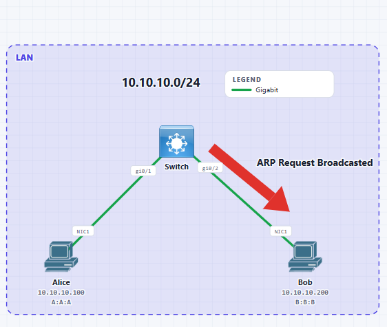
Keep in mind when the switch is flooding the broadcast message, it does not change, the L2 header is still all Fs as the destination MAC and the source MAC is A:A:A as we can see below. This is exactly still the same as it reaches towards Bob.
Remember in the above that the ARP data is including the Source MAC, Source IP, Target MAC and Target IP.
The switch basically floods this and it reaches Bob. Simple to understand. What's critical to understand is every host that receives a broadcast message MUST open up the frame and check what is inside it. In this case the ARP Request. They will determine if the message is for them, if not they will discard the message, otherwise they will process it, as explained below.
Bob opens up (de-encapsulates) the L2 header. By this, we mean it removes the outer destination MAC (which was all F's) and the source MAC it removes both and looks inside to see the ARP request message. Here is the magic, it checks and sees the Target IP address is for its own IP Address so this is how it knows that this message is for itself.
Bob also understands ARP so Bob knows hey this Target IP is for me so this ARP request was for me.
Same LAN Communication - Reverse Path
In the above we have discussed from one device to another the path it takes. Now we will discuss the reverse path, where Alice has sent the message to Bob, but Bob now needs to send a response back to Alice.
ARP Reply
As discussed Bob has now received an ARP Request from Alice and knows to fill in the Target MAC Address section. Bob does this and now we are presented with something known as the ARP Reply Message.
Below is Bob's ARP Reply Message Structure:
- Sender MAC - Now the Sender MAC is B:B:B because Bob's NIC is generating the ARP Response
- Sender IP - Now the Sender IP is 10.10.10.200 because Bob's NIC is generating the ARP Response
- Target MAC - Now the Target MAC is A:A:A - This is interesting...Bob knows Alice's MAC Address because it got it from both the L2 Frame that the broadcast came from, but also from the ARP Request Message. This is going to be the Original Sender's Source MAC Address.
- Target IP - Now the Now the Target IP is 10.10.10.100. It knows this from the ARP Request Message. This is going to be the Original Sender's Source IP Address.
As we know by now, this ARP reply will need a L2 Destination MAC Address to go onto the Ethernet Wire. However, we already know the Destination MAC as we got it from the initial ARP Request. So the frame looks like the below:
This can now go over the wire and get to the switch.
Switch CAM Table
When Bob sends the ARP Reply back to the switch via the L2 frame on the Ethernet Wire, the switch gets this and then logs in its MAC Address table that it has now learnt B:B:B (Bob) via Gi0/2. How does it know this? It looks into the L2 Frame and can see the Source MAC Address. And how is the MAC/CAM table populated? That's right, via the Source MAC Address.
Because of this the table now looks like:
| 1 | A:A:A | Gi0/1 |
| 1 | B:B:B | Gi0/2 |
No matching rows.
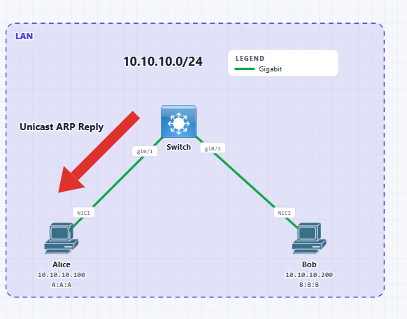
What makes the switch so great is that since the L2 Frame it receives now also has a populated destination MAC that matches A:A:A and earlier it learnt A:A:A was attached to its Gi0/1 interface. So instead of flooding out of all ports, it instead sends a unicast request back to Alice directly. This means ARP Reply is always a unicast message. This can be seen in the diagram below:
Sending the Ping Message
Finally, we get back to the initial Ping Message that Alice wanted to send to Bob. For a reminder, this is what it looked like:
Within the IP/Data we had the ICMP message as well as the source and destination IP Address but we couldn't forward this L2 Frame over the Ethernet Wire since we didn't know what the Destination MAC Address was. So it was saved in Alice's Memory.
Alice can now update the Destination MAC Address because it has now got the Unicast ARP Reply which resolved 10.10.10.200's/Bobs IP Address to its MAC Address of B:B:B. It essentially opened up the unicast ARP Reply and now knows Bob's MAC.
Now this Frame that contains the Ping Data looks like the below:
This L2 frame is forwarded to the Switch. The switch checks it MAC Address table and sees to reach the destination B:B:B it must send it via Gi0/2. It has already Learnt MAC A:A:A so no need to relearn.
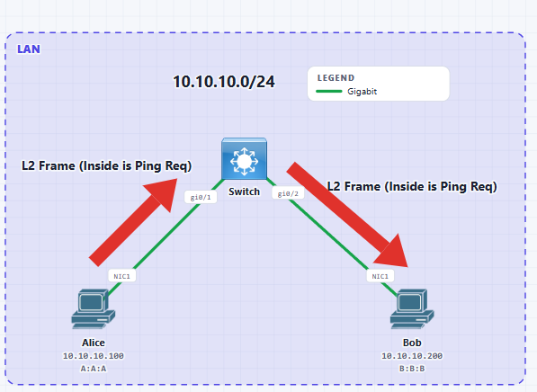
It forwards the frame out of Gi0/2 and Bob receives it. Bob de-encapsulates the L2 header and then checks the L3 Header. This is important, it checks hey this is for My IP Address, and then it de-encapsulates further to see the ICMP/Ping Request and will initiates its reply. We can see this illustrated in the diagram below:
Ping Reply messages
As mentioned Bob de-encapsulates the L2 header and L3 Header and checks and sees the Ping request. It then attempts to send back a response. Now is where the source and destination IP addresses change when Bob re encapsulates the Ping Message with a L3 header.
Note
From source to destination the IP Header does not change across hops!! However when the destination gets the packet and wants to send a response then yes, the Source and Destination in the IP Header is reversed! Critical to understand
At Layer 3 the above is what the packet will look like. When it needs to go over the wire it will be encapsulated in a L2 Frame which will look like the below:
Now the frame is sent to the switch. I will show the Switch's MAC table again:
| 1 | A:A:A | Gi0/1 |
| 1 | B:B:B | Gi0/2 |
No matching rows.
The switch already knows Alice's MAC. How? From the initial ARP Request. It then forwards the new L2 frame to Alice as a unicast frame. Alice then de encapsulates this frame and sees that the L3 Header is destined for her, and then de encapsulates further and checks the Ping/ICMP message and now we have full connectivity at L2 and L3 between these two hosts.
ARP Cache
The final concept we will be going over is the ARP Cache. It would be highly inefficient if we had to do a broadcast every time we needed to resolve an IP-to-MAC. Instead, when the host initiates the ARP and the process is complete, then this ARP is cached into the memory of the host device.
Typically this lasts for around 4 hours. This means for subsequent packets that come in, it will check hey do I know the MAC address of this destination IP address? And absolutely yes it does. it will encapsulate it into a L2 Ethernet frame and set the destination MAC according to tis ARP cache and forward the message. No need to redo the whole ARP process.
L2 and L3 Process of communication
Below is a High level process overview of how communication happens between two devices on the same LAN (and assuming no VLANs):
- 1Initiate Ping or Application creates data
- 2Encapsulated into a L3/IP Header
- 3Packet is encapsulated into a L2 Frame
- 4L2 Frame needs destination MAC. If it doesnt know, it saves the frame in memory
- 5ARP Request Process begins -> Broadcasted to the Switch
- 6Switch Learns the hosts MAC and puts in MAC table
- 7Switch Forwards broadcast message out of all ports except the one it learnt on
- 8Destination receives the broadcast frame and de encapsulates
- 9Destination sends an ARP Reply
- 10Switch learns the destination's MAC Address -> Unicast ARP sent to original sender
- 11ARP is now complete and both sides can exchange data
Wireshark PCAPs
Here I have used Pnetlab to generate the Ping and ARP messages in this Network. The only difference is that the MAC's in these Wireshark Captures from what we have previously discussed:
| Alice | 10.10.10.100/24 | 00:50:79:66:68:19 |
| Bob | 10.10.10.200/24 | 00:50:79:66:68:1a |
No matching rows.
This PCAP was taken from Alice's host. Before I took it, i went onto the switch and vpc and issued the command "clear arp".
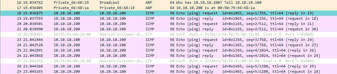
Here we can see the ARP Broadcast message and the ARP reply message. What initiated this was the Ping Alice's host ran. The ping was destined to 10.10.10.200 which is Bob. However at this point we don't know Bob's MAC Address so we had to send an ARP request and Cache the initial packet in memory.
ARP Request Packet
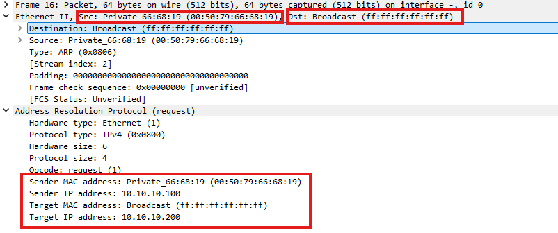
Above is the packet and within it we can see that we can see the Ethernet Frame. We can see the source is Alice's MAC and the destination frame is all F's. We can also see all the key parts of the ARP packet.
ARP Reply Packet
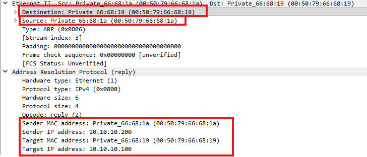
We do not see it, but the switch forwarded the broadcast to Bob, and we can see in the ARP reply at the L2 Ethernet Frame the destination is set to ALICE, with the source coming from Bob.
We can also see Bob has filled in his section of the Target MAC Address section. The Private_66:68:19 has to do with Wireshark and MAC addresses. We wont dive into the components of MAC Addresses.
Ping Request Packet
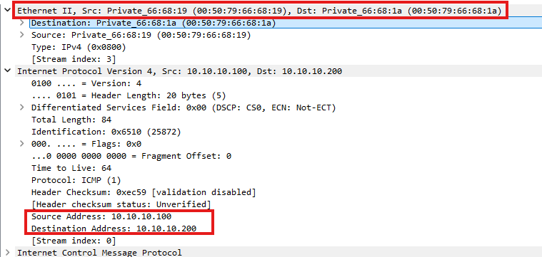
After the Address Resolution completed we can see that Alice fills in the destination MAC of her initial packet she wanted to send with Bob's MAC Address and sends the packet to Bob. This is a unicast message because it knows where Bob lives and the switch knows how to forward to Bob.
Ping Reply Packet
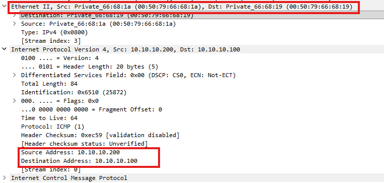
Finally we can see the reply back from Bob to Alice.
Comments