Please review the previous blog in this fundamental series before proceeding.
What is the Internet?
The internet is simply an interconnection of multiple different networks. Within each of these networks predominantly the technology they will run inside is Ethernet, and we have already discussed how hosts communicate within the same LAN. We use ARP broadcasts to learn MAC addresses of the destination host and use this to forward L2 frames. Simple enough.
However, this does not scale between networks. Lets say we have Alice in the UK and Bob in USA. They are geographically dispersed. It is not feasible to send a broadcast message to the entire internet just to get Bob's MAC Address. That would be very inefficient and because every switch/host has to process ARP in its CPU, it would be CPU intensive. Other issues with this is security concerns, you would not want to broadcast an ARP so that everyone in the world can know what Alice's MAC/IP is. Its just not feasible. This is fine in a LAN but not on the internet.
Separate LAN Communication
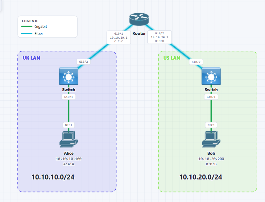
Here we have introduced a Router. A Router is a Layer 3 device. Unlike a standard L2 switch, a Router is special in that it can understand Layer 3 as well as Layer 2.
I have defined in this topology the Gi0/1 Fibre link between the Router and the UK LAN as 10.10.10.0/24. Similarly for the US LAN I have put the Gi0/2 Fibre link as 10.10.20.0/24.
These are both separate networks and separate LANs. For now I still have Alice and Bob but in reality we would have multiple different hosts in each of the LANs.
When Alice generates pings towards 10.10.20.200/24 her NIC will immediately will compare it to its own networks subnet mask and will determine that the destination is outside of her network. How it determines this is outside the scope. However, if curious the answer is XOR/AND operations. The host can determine this. You can read further in the recommended resources section.
Operations of a router
A routers job at a high level is to connect two or more networks together. Because it has cables into two different networks, it knows about these networks.
It is the administrator who statically assigns these networks to the router. Technically, you can use DHCP also to define networks on the routers interfaces but its not common.
Every interface on a router that is in use needs to be in a different network. They must have different IP's and it can be any host IP within that network address range. As long as there is no IP conflicts.
The router in essence has the below routing table once you have defined networks on its interfaces.
| Gi0/1 | 10.10.10.0/24 | Connected |
| Gi0/2 | 10.10.20.0/24 | Connected |
No matching rows.
Note
The routing table is not always just connected routes. Routers usually have static routes, or routes learnt from a dynamic routing protocol which we will learn about later.
Also something I've not mentioned before but L2 switches do not participate in ARP they just flood ARP requests. They have no ARP cache. We will see that routers are different and they have an ARP cache.
L3 switches can have an ARP cache however.
How host communicates with Default Gateway
Alice will send an Ping request to Bob who is in a different network. The L3 packet looks like the below:
The host Alice has already determined (as mentioned earlier) that the destination is in a different network. This means Alice knows for sure she cannot find this destination host within her own network. This is where the default gateway comes in.
The default gateway is used when a host is certain that the destination IP address does not belong within its own LAN. It uses this default gateway as someone who can forward these packets/frames on its own behalf. In this case the default gateway is the router. This can be set pretty much on any device with a NIC card, even most IP phones will have an interface to set this default gateway.
It CANNOT do an ARP Request with a Target IP of 10.10.20.200 because nobody on the LAN will know it. Another reason is broadcast packets are stopped at the router they cannot cross the router's boundary.
However we will take this L3 IP packet and we need to encapsulate it into an L2 frame because the switch it is connected to is an Ethernet switch which does not understand IP. We can see what it will be like below:
The source MAC is Alice's MAC Address A:A:A while the destination MAC of this L2 Frame is unknown Why? Because we don't know what R1's MAC is. We know we have to send it to R1 but we don't know what R1's MAC is from Alice's perspective. This current frame will be stored in memory and then the the ARP Message generated will look like the below:
This ARP packet is then further encapsulated into a new L2 Ethernet Frame as shown below:
The destination MAC is all F's so that the switch will flood it to everyone. This means that the Router's Gi0/1 interface receives this and De-encapsulates the frame and removes the outer L2 Header. The router will see that the Target IP in the ARP message is for 10.10.10.1 which is for its own IP and it will generate the below ARP Reply message:
This is then re-encapsulated into an L2 frame with the below:
The switch receives this and below is now the full MAC/CAM table of the switch:
| gi0/1 | A:A:A |
| Gi0/2 | C:C:C |
No matching rows.
It learnt C:C:C because of the unicast ARP reply from the router. The L2 frame is sent on the wire, hits the switch. The switch sees the source/destination MAC of the frame, populates the MAC table with the source MAC and then will flood it to Alice.
How hosts communicate outside
We have seen from the above that Alice has now got the MAC Address of its default gateway from the ARP Reply.
It will put this MAC Address into the initial L3 packet/Frame it created that has the ICMP/Ping information and send it on the wire towards the router. Below is what it looks like:
The router has an RJ45/Ethernet port on its end so it can see the L2 frame which it then de-encapsulates and then looks at the Layer 3 Header information. For a refresher the L3 Header is the below:
The IP DOES NOT change once at the router. The router will check in its routing table hey do I have a route towards 10.10.20.200/24? It checks its routing table and yes! It does have a route. See below:
| Gi0/1 | 10.10.10.0/24 | Connected |
| Gi0/2 | 10.10.20.0/24 | Connected |
No matching rows.
It now knows to get to 10.10.20.0/24 I must send this packet out of Gi0/2. But here's the problem, this needs to go out via an Ethernet Wire, and as we understand by now, Ethernet does not understand IP. So once again we need to encapsulate this same IP packet into a L2 Frame. And what's the problem with this? It does not know 10.10.20.200's MAC Address!
So the result is R1 will cache the packet currently in its memory and prepare an ARP request. The ARP Request will look like below:
This needs to be encapsulated into a L2 Frame. The Frame will look like the below:
This is critical to understand that the source MAC is now the routers Gi0/2 interface as the ARP request is being sourced on this interface.
This new switch receives the ARP Broadcast Frame and will flood it out of all its interfaces except the one it received it on. Meaning it will flood it to Bob. And then Bob will de-encapsulate the L2 Header since its a broadcast frame and inside it will check the ARP message and see the Target IP is destined for itself.
This means Bob will now prepare an ARP reply back towards the router. The ARP Reply will look like this:
Its important to note that the Target IP is defined for the router NOT for Alice. This is just an ARP reply Bob has not even got the original message from Alice yet so it doesnt know Alice's message.
Anyhow, this is a unicast ARP message sent to the Router. The switch receives this, and looks in its MAC/CAM table and it learns Bob via the L2 header, and populates it into the switches MAC table. Then it will check for the destination MAC. As we can see below it knows this:
| gi0/1 | B:B:B |
| Gi0/2 | D:D:D |
No matching rows.
Because the L2 header says to forward to D:D:D the switch does this. The router now receives this L2 frame and decapsulates it. It removes the L2 header and sees in the ARP message the MAC for 10.10.20.200 which is B:B:B.
Now the router can fill in the initial L2 Frame IP it had saved in memory(the one with the ping) with Bob's MAC Address as seen below:
The switch will just forward this L2 Frame as usual. When Bob receives this they will de-encapsulate the L2 Header and look inside and see the original L3 IP Header and will first check is this destination IP Address for me? And absolutely it is for Bob because it includes Bob's IP in the destination field.
Reverse Flow
Once the initial packet flow from source to destination is confirmed then essentially the communication channel is set up.
Bob will send back an ICMP/PING Reply message in response to the PING Request it got from Alice. The reply is exactly the same process EXCEPT there are a few subtle differences.
First Bob already knows the MAC for its default gateway which it knows it needs to go through in order to send this reply. Essentially the source and destination in the L3 Header is reversed. It will look like this:
This will then be encapsulated into a L2 Ethernet Frame that will look like the below:
There is no more need to do ARP. Bob will have Routers MAC in its ARP Cache and send this L2 Ethernet Frame towards the L2 Switch. This Switch checks is MAC table and no flooding/broadcast needed as it knows how to forward it to the Router.
The router receives this L2 Frame, de-encapsulates the L2 Header and checks the L3 IP header. Checks its routing table and knows how to forward to Alice. The whole process is done again.
I will summarise, the Router will check to get to Alice the packet needs to go out of Gi0/1. However, since its Ethernet the L3 Packet encapsulated into a L2 Ethernet Frame and sent on the wire. The Router has an ARP cache and already knows Alice's MAC. Its mapped this to Alice's IP which it knows from the L3 header. Anyway, the switch receives this and then forwards onto Alice who de-encapsulates the L2 header and checks that the L3 header and sees the destination IP is for her. She then further de-encapsulates and sees the ICMP/PING Reply message.
And this is how the full communication between devices on different networks happen in a nutshell if a router is connected to these two networks.
I have reiterated ARP and Ethernet encapsulations many times and that's because underneath this is what is happening. It's very logical operations happening and its something I wish someone had taught me much earlier.
Comments