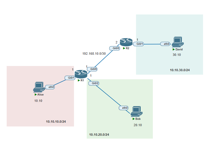
Topology Diagram
Note
Note that between R1 and R2 I have selected a /30 subnet. A /30 provides 2 hosts and is perfect for such a scenario when we have two routers connected.
3.3.d Floating static & Static Routing
Static Routes
As mentioned in 3.1 Interpret the components of routing table to reach destinations that are not directly connected, one of the easiest ways is through static routes where the administrator statically tells this router how it can reach the destination network and through which interface.
Warning
Static routes require both sides to be configured. In this example R1 needs to know the route to 10.10.30.0/24 and R2 needs to know the route to 10.10.10.0/24 to facilitate the communication between them both.
For small networks this is fine, for medium/large networks this is not scalable.
R1 Configuration:
R1(config)#ip route 10.10.30.0 255.255.255.0 192.168.10.2 <- We are saying to reach 10.10.30.0/24 we must go via next hop 192.168.10.2**R2 Configuration:**
R2(config)#ip route 10.10.10.0 255.255.255.0 192.168.10.1
R2(config)#do wrAlice pinging David:
Alice> ping 10.10.30.10

84 bytes from 10.10.30.10 icmp_seq=1 ttl=62 time=3.682 ms
84 bytes from 10.10.30.10 icmp_seq=2 ttl=62 time=2.535 ms
84 bytes from 10.10.30.10 icmp_seq=3 ttl=62 time=0.910 ms
84 bytes from 10.10.30.10 icmp_seq=4 ttl=62 time=1.358 ms
84 bytes from 10.10.30.10 icmp_seq=5 ttl=62 time=1.783 ms
David pinging Alice:
David> ping 10.10.10.10

84 bytes from 10.10.10.10 icmp_seq=1 ttl=62 time=1.631 ms
84 bytes from 10.10.10.10 icmp_seq=2 ttl=62 time=1.555 ms
84 bytes from 10.10.10.10 icmp_seq=3 ttl=62 time=1.616 ms
84 bytes from 10.10.10.10 icmp_seq=4 ttl=62 time=0.844 ms
84 bytes from 10.10.10.10 icmp_seq=5 ttl=62 time=1.540 ms
We now have achieved two way communication across these two separate networks. But how is this actually working?
Packet Flow
Alice will generate the ICMP ping message. The L3 packet information will be like the below:
I wont include it, but Alice knows this destination is not part of her network due to the subnet mask. It basically does some XOR/AND operations (outside of this scope) in order to determine if a destination IP is for this network or for another network.
Alice will then encapsulate this into a L2 Ethernet Frame and send this to her default gateway which is R1.
R1 then strips the L2 ethernet header and looks into the L3 header and sees the destination IP address and does a routing table lookup:
      10.0.0.0/8 is variably subnetted, 5 subnets, 2 masks
C        10.10.10.0/24 is directly connected, GigabitEthernet0/1
L        10.10.10.1/32 is directly connected, GigabitEthernet0/1
C        10.10.20.0/24 is directly connected, GigabitEthernet0/2
L        10.10.20.1/32 is directly connected, GigabitEthernet0/2
S        10.10.30.0/24 [1/0] via 192.168.10.2 <- Administrator defined static route
      192.168.10.0/24 is variably subnetted, 2 subnets, 2 masks
C        192.168.10.0/30 is directly connected, GigabitEthernet0/0
L        192.168.10.1/32 is directly connected, GigabitEthernet0/0
R1#
It know if it wants to route this packet it should go via R2 which is 192.168.10.2. It encapsulates the packet into an ARP request. R1 ARPs for R2's MAC Address and this works because R1 knows that the destination IP should be, and its filled inside the ARP's Target IP feild. Anyway, once ARP is done the frame is forwarded to R2.
R2 encapsulates the frame and checks for the destination network. We can see R2's Routing table:
      10.0.0.0/8 is variably subnetted, 3 subnets, 2 masks
S        10.10.10.0/24 [1/0] via 192.168.10.1
C        10.10.30.0/24 is directly connected, GigabitEthernet0/1 <- Connected route to 10.10.30.0/24
L        10.10.30.1/32 is directly connected, GigabitEthernet0/1
      192.168.10.0/24 is variably subnetted, 2 subnets, 2 masks
C        192.168.10.0/30 is directly connected, GigabitEthernet0/0
L        192.168.10.2/32 is directly connected, GigabitEthernet0/0
The route lookup confirms there is a connected route to 10.10.30.0/24. All R2 needs to do now is a repeat of ARP and then it can forward the L2 frame to David at 10.10.30.10/24. Then the reverse happens with the ICMP reply occurs. ARP still needs to be done again but after this first initial request and reply the communication is built and no more ARP.
Default Route
Lets say we have connected R2 to the internet, this can contain hundreds if not millions of networks belonging to Amazon, Google, Microsoft etc. Services that we want to be able to reach. Configuring static routes to each of these destinations is nigh on impossible. They would also need static routes back to your public IP prefixes as well.
So in our example, we know that these destinations are not connected to any of our devices and that to reach them we need to go out via R2. So we can use something called a default route.
Definition
A default route allows for sending traffic to a next hop, if that traffic does not match any network in this routers routing table.
This default route allows for letting R1 know to reach Amazon, Google, Microsoft or anything else it does not know or have a route to, forward it to R2. How R2 learns the IP addresses of all these services is outside of this scope. But for your awareness it is through a routing protocol known as BGP which is outside of this scope.
To configure a default route is below:
R1(config)#ip route 0.0.0.0 0.0.0.0 192.168.10.2
R1(config)#do sh ip route
Codes: L - local, C - connected, S - static, R - RIP, M - mobile, B - BGP
       D - EIGRP, EX - EIGRP external, O - OSPF, IA - OSPF inter area
       N1 - OSPF NSSA external type 1, N2 - OSPF NSSA external type 2
       E1 - OSPF external type 1, E2 - OSPF external type 2
       i - IS-IS, su - IS-IS summary, L1 - IS-IS level-1, L2 - IS-IS level-2
       ia - IS-IS inter area, * - candidate default, U - per-user static route
       o - ODR, P - periodic downloaded static route, H - NHRP, l - LISP
       a - application route
       + - replicated route, % - next hop override, p - overrides from PfR

Gateway of last resort is 192.168.10.2 to network 0.0.0.0 <-Notice this was unset before

S*    0.0.0.0/0 [1/0] via 192.168.10.2
      10.0.0.0/8 is variably subnetted, 5 subnets, 2 masks
C        10.10.10.0/24 is directly connected, GigabitEthernet0/1
L        10.10.10.1/32 is directly connected, GigabitEthernet0/1
C        10.10.20.0/24 is directly connected, GigabitEthernet0/2
L        10.10.20.1/32 is directly connected, GigabitEthernet0/2
S        10.10.30.0/24 [1/0] via 192.168.10.2
      192.168.10.0/24 is variably subnetted, 2 subnets, 2 masks
C        192.168.10.0/30 is directly connected, GigabitEthernet0/0
L        192.168.10.1/32 is directly connected, GigabitEthernet0/0
R1(config)#
Note that 0.0.0.0 0.0.0.0 (also written as 0.0.0.0/0) is known as the "All IP Addresses" range. Everything matches to this route. This is known as the default route, gateway of last resort or default gateway. Most common saying is default route or default gateway. Its essentially saying if I don't know where to forward the packet then to forward to this next hop.
Tip
Usually an ISP will provide a modem/ONT of some kind. An ONT is for Fibre optics and modem for Ethernet cables. They plug a cable from the customers router's WAN/Internet port into the modem/ONT box. This convers the signal and then connects to those green boxes you see outside. These are the distribution points where the ISP network fans to individual homes or businesses in the neighbourhood. This is just a overview of it of how a device can provide internet connectivity.
Default Route on endhosts
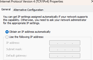
This screenshot the entries are blanked because it is using DHCP to obtain an IP Address. However, if it was statically assigned IP address (like you'd see on a server) then we would manually set the default gateway.
What is happening here is that an endhost at Layer 2 can communicate with other devices via a switch if on the same VLAN. However if they were segmented with different VLANs we would need a router/L3 device to route between the different VLANs. This is where default route is useful for an end device. It can craft a packet and send it to its default gateway to handle the packet. The router then checks its routing table for the end destination. If it doesn't have it then it drops it. Alternatively if the end host wants to communicate externally to the internet it also sends packets it generates via the application layer towards the router.
Note
For awareness DHCP also does set the default gateway to clients who lease addresses from it. But that is outside of scope.
Longest Match Route
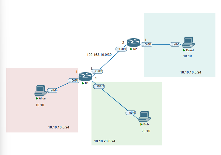
Here I have changed the topology slightly. R1 and R2 both have connected networks to 10.10.10.0/24. These connected routes will always be the most preferred type of route. This was briefly discussed in 3.1 Interpret the components of routing table
What if we have a case like the below on R1:
      10.0.0.0/8 is variably subnetted, 6 subnets, 5 masks
S        10.10.10.0/24 [1/0] via 192.168.10.2
S        10.10.10.0/25 [1/0] via 192.168.10.2
S        10.10.10.0/26 [1/0] via 192.168.10.2
S        10.10.10.0/27 [1/0] via 192.168.10.2
Since these are all separate networks ALL of them get inserted into the routing table and go out via the next hop which is R2. If they were all the same network we wouldn't have these separate entries. If they were however the same network but learnt via different sources (such as EIGRP or OSPF) then administrative distance would determine which one of the two (or more) routes are installed in the routing table.
If we have a packet that comes into R1 that is destined for 10.10.10.10 which one does it match? In this case it matches the one with the most specific or longest match in this case 10.10.10.0/27 as that includes from .1 - .30 as useable host addresses. And 10.10.10.10 matches this so it egresses out of this interface/next hop.
If we have more network bits we have less host bits. This makes it more specific.
Load Balancing
Here is our new network topology.
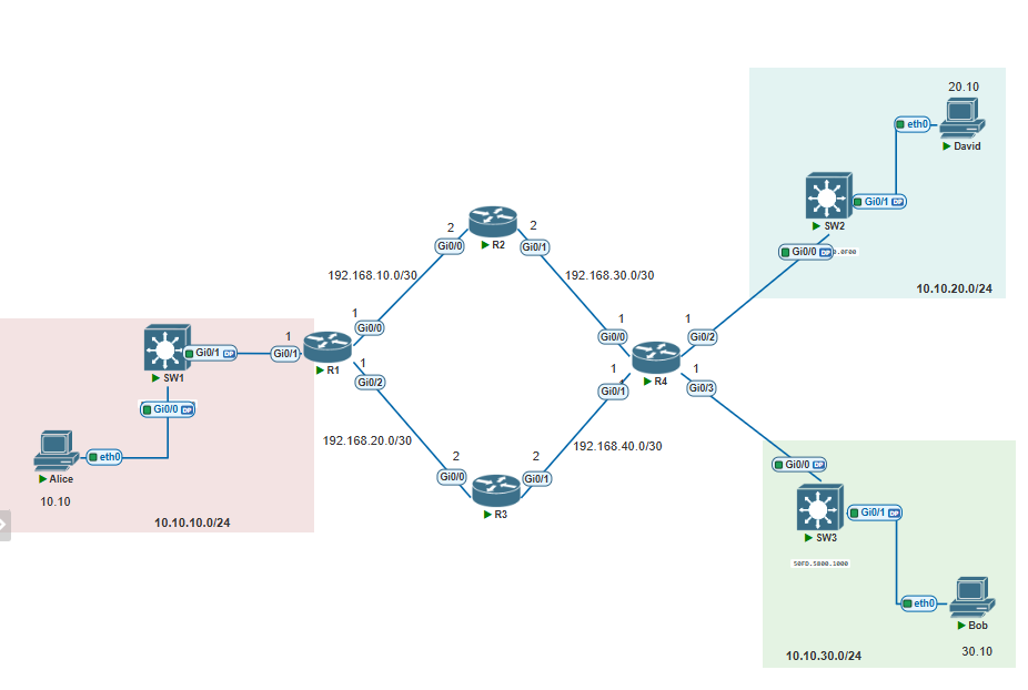
We have R1 - R4. On R1 I have created these static routes towards 10.10.10.0/24:
R1(config)#ip route 10.10.20.0 255.255.255.0 192.168.10.2
R1(config)#ip route 10.10.20.0 255.255.255.0 192.168.20.2
R1(config)#end
R1#show ip route
Codes: L - local, C - connected, S - static, R - RIP, M - mobile, B - BGP
       D - EIGRP, EX - EIGRP external, O - OSPF, IA - OSPF inter area
       N1 - OSPF NSSA external type 1, N2 - OSPF NSSA external type 2
       E1 - OSPF external type 1, E2 - OSPF external type 2
       i - IS-IS, su - IS-IS summary, L1 - IS-IS level-1, L2 - IS-IS level-2
       ia - IS-IS inter area, * - candidate default, U - per-user static route
       o - ODR, P - periodic downloaded static route, H - NHRP, l - LISP
       a - application route
       + - replicated route, % - next hop override, p - overrides from PfR

Gateway of last resort is not set

      10.0.0.0/8 is variably subnetted, 3 subnets, 2 masks
C        10.10.10.0/24 is directly connected, GigabitEthernet0/1
L        10.10.10.1/32 is directly connected, GigabitEthernet0/1
S        10.10.20.0/24 [1/0] via 192.168.20.2
                       [1/0] via 192.168.10.2
In this case there are two valid paths to reach 10.10.20.0/24 - Via R2 (192.168.10.2) and Via R3(192.168.20.2). Since these are the same routing protocol Administrative Distance is not a factor. Metric is also the same for both these routes. So which one is used? Well, this is where the router allows for something called "per-packet load balancing".
So if we have two packets with different source addresses going to the same destination address of 10.10.20.0/24, then first packet may go via R2, second packet via R3, third packet via R2 and so on giving an even 50/50 split which is a round-robin per-packet load balancing style.
However this is not an efficient as a endpoint may not be delivering just a single packet but maybe hundreds of packets to 10.10.20.0/24, we can have "same-flow load balancing" where no matter how many packets Alice at 10.10.10.10/24 sends to David at 10.10.20.10/24, they will always follow the SAME path. If the router determines this flow to go over R2 as long as that flow/session is alive it will go over R2.
Floating Static Routes
While this load balancing is great, what if we do not want this? What if we have a requirement to only allow ALL traffic to go via R2? We are required to only have R3 as a backup router. In this case if R2 goes down, or a link goes down, we want traffic to then fall back (or failover) to R3.
This is basically referring to primary and secondary path flow. This may be where the primary is 10Gig interface and secondary is only 1Gig link. If something happens to the 10Gig then the secondary should come up.
There are many ways to achieve redundancy in a network. But in terms of routing, one thing we can do is play with the metric values. With a static route, all static routes have a metric value of 1 by default. This means if we have two static routes to the same destination they will load balance. To break this, and have redundancy we modify this administrative so that it is higher than 1. You can see this below:
R1(config)#ip route 10.10.20.0 255.255.255.0 192.168.20.2 10This 10 value is assigning an AD value of 10 to this route. If we now look into the routing table, we wont see this route:
R1#show ip route
      10.0.0.0/8 is variably subnetted, 3 subnets, 2 masks
C        10.10.10.0/24 is directly connected, GigabitEthernet0/1
L        10.10.10.1/32 is directly connected, GigabitEthernet0/1
S        10.10.20.0/24 [1/0] via 192.168.10.2
      192.168.10.0/24 is variably subnetted, 2 subnets, 2 masks
C        192.168.10.0/30 is directly connected, GigabitEthernet0/0
L        192.168.10.1/32 is directly connected, GigabitEthernet0/0
      192.168.20.0/24 is variably subnetted, 2 subnets, 2 masks
C        192.168.20.0/30 is directly connected, GigabitEthernet0/2
L        192.168.20.1/32 is directly connected, GigabitEthernet0/2
R1#
We only see the route going via 192.168.10.2. If this link was to go down then we would see the link via R3 coming up as we see here:
*Aug  3 23:20:47.712: %LINEPROTO-5-UPDOWN: Line protocol on Interface GigabitEthernet0/0, changed state to down
*Aug  3 23:20:48.715: %LINK-3-UPDOWN: Interface GigabitEthernet0/0, changed state to down

R1#show ip route
      10.0.0.0/8 is variably subnetted, 3 subnets, 2 masks
C        10.10.10.0/24 is directly connected, GigabitEthernet0/1
L        10.10.10.1/32 is directly connected, GigabitEthernet0/1
S        10.10.20.0/24 [10/0] via 192.168.20.2
      192.168.20.0/24 is variably subnetted, 2 subnets, 2 masks
C        192.168.20.0/30 is directly connected, GigabitEthernet0/2
L        192.168.20.1/32 is directly connected, GigabitEthernet0/2
R1#Tip
Lower AD value is always preferred. Giving any type of route a higher AD value will make it less preferred. Floating static route is a static route with a higher administrative distance thus making it less preferred.
Comments