Topology
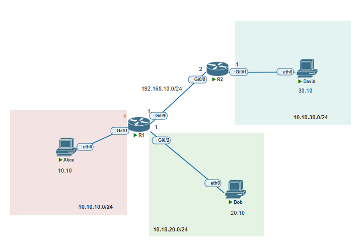
This is the topology we will be using:
Tip
In many real world networks typically the .1 address of each network is assigned to the router interface or the VLAN Sub interface. Its very common. But this is not the rule, it can be any IP within that network range besides he network address and the broadcast address all others are allowed.
Routing table
A switch will store source MAC Addresses in its MAC Address table from incoming frames that it receives. It uses this to populate this MAC table in order to forward Layer 2 Ethernet Frames over the Ethernet wire. This is the database Switches use.
However, a Router is a L3 device and it uses IP addressing as its PDU. The database we have at Layer 3 is known as the routing table. Within the routing table we store information related to networks.
Connected Routes
As soon as you configure an IP address/network on a router's interface it becomes a connected route. A connected route is saying that through this interface, this specific network is available.
I have configured on R1 & R2 their respective interface IPs/networks as below:
R1 Configuration:
R1(config)#int gi0/1
R1(config-if)#no shut
R1(config-if)#ip add 10.10.10.1 255.255.255.0
R1(config-if)#int gi0/2
R1(config-if)#no shut
R1(config-if)#ip add 10.10.20.0 255.255.255.0
Bad mask /24 for address 10.10.20.0 <- Notice how if you specify the network address of this /24 on an interface it gives this error. This is because network address is reserved.
R1(config-if)#ip add 10.10.20.1 255.255.255.0
R1(config-if)#end

R1#
R1 Verification:
R1#show ip interface brief <- Use this command to verify IP configuration on interface
Interface                  IP-Address      OK? Method Status                Protocol
GigabitEthernet0/0         unassigned      YES unset  up                    up
GigabitEthernet0/1         10.10.10.1      YES manual up                    up
GigabitEthernet0/2         10.10.20.1      YES manual up                    up
GigabitEthernet0/3         unassigned      YES unset  administratively down down
R1#R1#show ip route <- this shows the routing table
Codes: L - local, C - connected, S - static, R - RIP, M - mobile, B - BGP
D - EIGRP, EX - EIGRP external, O - OSPF, IA - OSPF inter area
N1 - OSPF NSSA external type 1, N2 - OSPF NSSA external type 2
E1 - OSPF external type 1, E2 - OSPF external type 2
i - IS-IS, su - IS-IS summary, L1 - IS-IS level-1, L2 - IS-IS level-2
ia - IS-IS inter area, * - candidate default, U - per-user static route
o - ODR, P - periodic downloaded static route, H - NHRP, l - LISP
a - application route
+ - replicated route, % - next hop override, p - overrides from PfR
<- these codes represent all the possible ways a route can be learnt
Gateway of last resort is not set
10.0.0.0/8 is variably subnetted, 4 subnets, 2 masks
C 10.10.10.0/24 is directly connected, GigabitEthernet0/1 <- the actual network connected
L 10.10.10.1/32 is directly connected, GigabitEthernet0/1 <- The host/IP address on the interface
C 10.10.20.0/24 is directly connected, GigabitEthernet0/2
L 10.10.20.1/32 is directly connected, GigabitEthernet0/2
192.168.10.0/24 is variably subnetted, 2 subnets, 2 masks
C 192.168.10.0/24 is directly connected, GigabitEthernet0/0
L 192.168.10.1/32 is directly connected, GigabitEthernet0/0
R1#R2 Configuration:
R2#conf t
R2(config)#int gi0/0
R2(config-if)#no shut
R2(config-if)#ip add 192.168.10.2 255.255.255.0
R2(config-if)#int gi0/1
R2(config-if)#no shut
R2(config-if)#ip add 10.10.30.1 255.255.255.0
R2(config-if)#
R2 Verification:
R2#show ip route
Codes: L - local, C - connected, S - static, R - RIP, M - mobile, B - BGP
       D - EIGRP, EX - EIGRP external, O - OSPF, IA - OSPF inter area
       N1 - OSPF NSSA external type 1, N2 - OSPF NSSA external type 2
       E1 - OSPF external type 1, E2 - OSPF external type 2
       i - IS-IS, su - IS-IS summary, L1 - IS-IS level-1, L2 - IS-IS level-2
       ia - IS-IS inter area, * - candidate default, U - per-user static route
       o - ODR, P - periodic downloaded static route, H - NHRP, l - LISP
       a - application route
       + - replicated route, % - next hop override, p - overrides from PfR

Gateway of last resort is not set

      10.0.0.0/8 is variably subnetted, 2 subnets, 2 masks
C        10.10.30.0/24 is directly connected, GigabitEthernet0/1
L        10.10.30.1/32 is directly connected, GigabitEthernet0/1
      192.168.10.0/24 is variably subnetted, 2 subnets, 2 masks
C        192.168.10.0/24 is directly connected, GigabitEthernet0/0
L        192.168.10.2/32 is directly connected, GigabitEthernet0/0
R2#
Next Hop
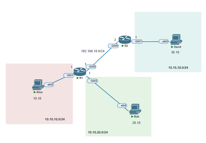
Refer back to this diagram. How can we reach 10.10.30.10/24 if it is not directly connected to any of R1's interfaces? This is where we have the ability to tell R1 out of which interface it can go to reach this destination via some other router.
We can tell it from which router it can reach this network. This is from this routers perspective. So we can tell R1 to reach 10.10.30.0/24 it can go via R2. We point to R2 as our next hop to reach this destination. What is the next hop? Is the interface through which we can reach the destination. In this case R1's next hop is the Gi0/0 interface of R2.
R2's GI0/0 interface has an IP address assigned to its interface which is 192.168.10.2/24. We are essentially saying, to reach David on 10.10.30.10 we must go through next hop 192.168.10.2/24.
Of course, this is then encapsulated into an L2 frame and sent on the wire. ARP used to find the destination MAC Address. This will never change in an Ethernet network.
R2 once it receives this L2 frame de-encapsulates it and looks in the L3 header and does a routing table lookup, known as a "FIB" or "Forwarding Information Base" lookup in which it checks the routing table for this entry.
- 1Application Layer generates the data
- 2TCP/UDP provides destination server IP
- 3At Layer 3 Source & Destination IP is put in the IP Header
- 4ARP required to find destination MAC addressAssume this process has completed
- 5Routers receive the L2 frame, de-encapsulate this frame, and check its routing tableRouting table lookup confirms where the destination is located and how to reach it
- 6Router needs to do ARP again to find destination MAC Address and put this into an L2 frame
- 7Steps 5-6 repeated until it reaches end router
- 8End router will have a connected route to the end destination
- 9ARP is used to find destination MAC Address -> Packet then forwarded to end destination
What if no next hop?
If a router does not have next hop information for a route, lets say in our example, if R1 receives an IP packet for 10.10.40.15/24, it will check its routing table and look for entries matching this subnet.
If there is no entry matching it, then the packet will be dropped at this router it wont be forwarded any further. Why? Because if not it cannot encapsulate the L2 frame into an ethernet frame and input the target IP within an ARP message for the next hop, because it doesn't know what next hop this network is known from!
Tip
A useful way to check for a matching route is to do something like this:
R1#show ip route 10.10.10.10
Routing entry for 10.10.10.0/24
  Known via "connected", distance 0, metric 0 (connected, via interface)
  Routing Descriptor Blocks:
  * directly connected, via GigabitEthernet0/1
      Route metric is 0, traffic share count is 1
R1#
As you can see we can specify the end destination with this command and see if this router knows how to reach it.
If we don't have a route we will see something like the below:
R1#show ip route 172.16.1.1
% Network not in table
Types of routes
As we have discussed already there are connected routes which we can use to forward traffic. However, this is only useful for traffic directly connected to this router. If we want to reach networks not connected to this router such as across a WAN connection then we need different types of routes. There 3 main types:
| 1)Connected | Network directly connected to this router on one of its interfaces | C | Configure an IP address within a subnet on one of the interfaces. Each interface MUST be unique subnets |
| 2)Static Routes | Administrator defined static route. This is a route not directly connected to any interfaces on this route. It is used to reach remote networks. This is not scalable | S | ip route [destination subnet] [subnet mask] [next hop IP] |
| 3)Dynamic Routes | Routes are learnt dynamically. They share information about their connected routes to eachother. | Dependant on routing protcol. May be O, R, I, D, B etc | Dependant on the routing protocol. |
No matching rows.
Administrative Distance
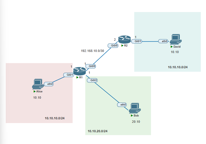
The topology has changed slightly now. Now we have two separate 10.10.10.0/24 directly connected to R1 and R2. Both same network and hosts ranges. Let's say we configure R1 to have a static route towards 10.10.10.0/24 on R2's side, and R2 is also using a routing protocol (like OSPF) to advertise 10.10.10.0/24 to R1, what would happen?
      10.0.0.0/8 is variably subnetted, 4 subnets, 2 masks
C        10.10.10.0/24 is directly connected, GigabitEthernet0/1
S        10.10.10.0/24 via GigabitEtherne0/0 <- This is via R2 static route
O        10.10.10.0/24 via GigabitEtherne0/0 <- This is via R2 Dynamic Route
Both these Red routes in this case would NOT show up in the routing table as you might expect. The network is the same across these different sources, however since the router must select ONLY one route to go into its routing table.
In this case, it selects (or prefers) a route based on Administrative Distance. The lower the number the higher the preference for this route. Below is the table of common AD values per route type.
| Connected Routes | 0 |
| Static Route | 1 |
| eBGP | 20 |
| Internal EIGRP | 90 |
| OSPF | 110 |
| IS-IS | 115 |
| RIP | 120 |
| iBGP | 200 |
No matching rows.
If the interface GigabitEthernet0/1 on R1 was to go down, the connected route to 10.10.10.0/24 would be removed from the routing table. This leaves us with the static route based on the prior configuration because this has more preference over the OSPF dynamic route based on its AD value of 1.
Longest Match Route
What if we have where the administrator Alice has removed the cable on R1 connecting to 10.10.10.0/24 and configured the below static routes:
R1(config)#ip route 10.10.10.0 255.255.255.0 192.168.10.2 <- /24
R1(config)#ip route 10.10.10.0 255.255.255.128 192.168.10.2 <- /25
R1(config)#ip route 10.10.10.0 255.255.255.192 192.168.10.2 <- /26
R1(config)#ip route 10.10.10.0 255.255.255.224 192.168.10.2 <- /27
Here she has configured these routes to go out via next hop R2 or maybe towards a different router. However, we can see from the subnet mask that these are different networks. What's critical to understand is every single one of these routes will be inserted into the routing table! Because they are all different networks.
Now we know that each route will be in the routing table, what happens when we get a packet that is destined for 10.10.10.10? How do we know which one of these routes it matches? The way this is determined is by the longest prefix match.
This is by the most specific subnet mask basically. 10.10.10.10 matches all 4 networks in the routing table, but the /27 is most specific. Within it it has 32 host networks from 10.10.10.1 - 10.10.10.31. This is more specific than the /24 which is 10.10.10.1 - 254 for hosts. This means R1 will select 10.10.10.0/27 as the next hop for this route.
This is shown below: *Aug 2 21:02:11.490: %LINEPROTO-5-UPDOWN: Line protocol on Interface GigabitEthernet0/1, changed state to down *Aug 2 21:02:12.490: %LINK-3-UPDOWN: Interface GigabitEthernet0/1, changed state to down <- Removed the connected route/cable R1#show ip route 10.0.0.0/8 is variably subnetted, 6 subnets, 5 masks S 10.10.10.0/24 [1/0] via 192.168.10.2 S 10.10.10.0/25 [1/0] via 192.168.10.2 S 10.10.10.0/26 [1/0] via 192.168.10.2 S 10.10.10.0/27 [1/0] via 192.168.10.2 R1#show ip route 10.10.10.10 <- this command allows us to check what destinaton matches which route. Routing entry for 10.10.10.0/27 Known via "static", distance 1, metric 0 Routing Descriptor Blocks:
- 192.168.10.2 Route metric is 0, traffic share count is 1 R1#
Comments