The problems with Layer 2 Networks
This is our topology. Just looking at it you can tell there is a physical loop. SW1 is connected to SW2, and SW2 connected to SW3 and SW3 connected back to SW1.
Alice and Bob are both part of VLAN 10 and in the same IP subnet. If Alice wants to ping Bob, well an ARP broadcast would have to be sent to SW1. SW1 will broadcast this out of Gi0/1 and Gi0/2 interfaces. We are assuming that SW1, SW2 and SW3 are all trunk links carrying VLAN10 otherwise it wont be broadcasted over those links.
| 10 | 00:50:79:66:68:1e | Gi0/0 |
| 10 | 00:50:79:66:68:1e | Gi0/2 |
No matching rows.
| 10 | 00:50:79:66:68:1e | Gi0/1 |
| 10 | 00:50:79:66:68:1e | Gi0/2 |
No matching rows.
| 10 | 00:50:79:66:68:1e | Gi0/0 |
| 10 | 00:50:79:66:68:1e | Gi0/2 |
No matching rows.
Can you see the problem from these tables? SW1 is flooding it to SW2 and SW3. SW3 will get this broadcast message and also flood it out of all ports except the one it received it on. Meaning it will be flooded from SW3 to SW2. When SW2 gets the frame it will flood it out of Gi0/2. SW3 will then flood it out of its gi0/0 and so on.
What we have now is a Layer 2 loop. What is critical to understand is that the Layer 2 Frame does not have any "expiry" mechanism that says that after so many "hops" this frame should be discarded. This will NEVER stop not until the resources (mainly CPU) of the switch are so overwhelmed that it crashes the switch. This is known as a broadcast storm and it happens when there is a Layer 2 loop in the network. It is also known as "MAC Address Flapping" where a MAC Address is flapping between being learnt on different ports.
The above table is not totally accurate but for demonstration to show how the same source MAC is being learnt on multiple different interfaces. In reality the MAC table would constantly re-update itself as it receives broadcast frames from the separate switches. So we would see 00:50:79:66:68:1e constantly being relearnt but on different ports. This is once again MAC Address flapping, where the same source MAC is learnt on different ports.
Since we are talking about ARP in this scenario, this is known as ARP flooding that is causing the loop.
Tip
In my experience (and many others) whenever you see a MAC-FLAP there is a layer 2 loop somewhere in the network. This can be complicated to find especially because in my experience it has always happened across port channels and can be quite challenging. Make sure to isolate the MAC's which are having the issues
How to break this loop?
I have pasted the topology again:
The easiest way to break this loop is lets say between SW1 and SW2 we remove the physical cable. This way if Alice sends an ARP request frame, SW1 will flood it to SW3 and SW3 will flood it to SW2 however SW2 will NEVER flood it back to SW3 here. Why? Because fundamental principle of switches is not to flood broadcast frames out of the same interface they received it on.
While this is absolutely the solution. There is an issue. What if the interface between SW1 and SW3 is a 10gig link, but from SW3 to SW2 a 10mbps link? If we remove the physical link between SW1 and SW2 then we have to go through this path that may not be optimal.
If SW1 to SW2 link is a 10gig interface, then taking this down would obviously be the least preferred option, because this is direct connectivity towards SW3 over a faster link than from SW1-SW3-SW2.
However, we also don't want to shut down the 10gig link between SW1 and SW3. So the best link to shut down here or remove would be the link connecting SW3 and SW2 - the 10mbps link. This is fine and does break the loop.
But, what if either of these 10 gig links end up going down in the future? Then how can we communicate to each other? We cant unless the 10mbps link is back up even if its not the greatest link it still allows the communication.
This is a great diagram below illustrating this:
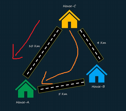
Here we have House-C and there are two paths in order for a person in House C to reach House A. At first they may decide the 10Km path is the best most direct path. However the path from House C -> House-B to House-A is actually 1km quicker. However, this path is two roads. This is the shortest path according to a GPS it would prefer to save you petrol and would go through the orange path. In networking terms we would call this the best cost shortest path.
Classic Spanning-Tree Protocol
Spanning-Tree protocol (STP) is a protocol/algorithm in every layer 2 switch imaginable. It is a vendor neutral protocol, it is also commonly referred to as 802.1D. It's purpose is to eliminate a loop in the network by shutting down/blocking a redundant path that can cause a loop but ensuring the best path is available. STP ensures that high capacity links are not accidentally shut down.
STP runs all the time on all L2 switches even between different vendors to ensure a L2 loop can never happen. All switches in an STP Topology or domain, we can call it either, participate together to confirm which ports should be blocked or allowed to prevent the L2 loop.
1) STP Root Bridge election
Before STP can work on blocking loops it must first pick a starting point to build the spanning-tree topology. This is where an election process occurs. This in the past was known as the root bridge (and still in many implementations it is still referred to as this), however nowadays we can refer to it as a Root Switch.
A bridge is an old legacy device which was first used when developing spanning-tree protocol. That is why we see the term "Root Bridge" instead of "Root Switch" even though we are running STP on a switch and not a bridge device.
Here is the same topology but I've modified it to include the Burned in MAC Address of the Switches. This is not referring to the interface MAC but the actual switch MAC address. You can find this in a show version or the label of the switch on the side of the box:
The process of Root Bridge Election is as follows:
- 1All switches on boot believe they are RootAll switches believe that they are the root bridge upon first boot. SW1, SW2 and SW3 in out topology will believe they are the Root Bridge.
- 2BPDU ExchangeThese switches should communicate with each other to decide instead who is the root bridge. The messages they send to each other are Bridge Protocol Data Units. All Layer 2 switches generates these BPDU's. The first BPDU is a message saying they believe they are the root bridge.
- 3MAC Address PreferenceRoot bridge is elected based on MAC Address. Every single switch will have a burned in SWITCH MAC Address! The smallest MAC Address wins the election. This MAC Address is included in the BDPU advertisement so all switches learn it. In our example SW3 has MAC of C:C:C so it is elected as the root bridge and all switches agree
- 4(Optional) - Manually picking root bridgeIf we don't want the software to pick the root bridge (there are reasons for this), we can assign this ourselves. With a switches MAC there is a number assigned to it. Default is 128 for all switches. This is known as priority, because of this MAC is the preferred one. We can make this priority number smaller to make a switch preferred and thus become the root bridge.
- 5Optional - spanning-tree vlan [vlan-id] root [Primary/Secondary]Optionally, if we do not want to mess around with the priority values we can just issue these commands on the specific VLAN's for which should be the spanning-tree root bridge and which should be the secondary. Concepts we will be discussing.
2) Root Ports
After the root bridge is elected we need to select ports which are near the root bridge. What this means is we have already selected the Root Bridge. What are the best links to get to this Root bridge. For example, what is SW1 and SW2's best path/links to get to SW3 which is the root.
Note
This Root Port theory applies to ALL NON-ROOT Bridge/switches.
I have modified the Diagram to include link costs:
SW1 shortest path to root
In the diagram we can see SW1 has two paths o reach to the root bridge. One directly via its Gi0/1 to get to the root switch and so the cost is 10. The other via Gi0/2 -> SW2 -> SW3, this paths cost is 5 + 10 = 15. Obviously the best path cost is the one directly from gi0/1 to SW3. This best path cost port is known as the "Root Port" .
The Root Port is important because it has the lowest "Distance" or "Cost" to reach to the root bridge.
SW2 shortest path to root
Similarly, the best path from SW3 to the Root Switch is via its Gi0/2 interface as the cost is 10. So this becomes SW2's Root Port.
Root Bridge BPDU
Once the Root Bridge Election is done ONLY the root bridge continues to generate the BPDU. Another thing to understand is that BPDU messages generated by the Root Switch is always coming with a cost of 0. Because its generated by the root itself, it does not need any cost/path to reach itself.
Tip
By the way, BDPUs are Layer 2 Ethernet frames they do not have any IP information
So, SW3 becomes the root and keeps sending BPDU's down to SW1 and SW2.
SW1 will get the BPDU and know on its Gi0/1 the link cost is 10. So from the BPDU from SW3, it will add 10 to the cost. Similarly same will happen from SW2, it will receive a BPDU from the root bridge with a cost of 0 and then it will add in the cost of 10 to that BPDU.
SW1 and SW2 will never generate BPDU's themselves they will FORWARD the initial BPDU.
This means when SW1 forwards the BPDU to SW2, SW2 will receive it on its gi0/1 interface and then SW2 will add the cost of 5 to it. This means this BPDU SW2 got has a cost of 10 + 5 which is 15 and of course this is less than its root port. Same thing will happen when SW2 forwards its BDPU to SW1.
Below is summary of the process:
- 1Root Bridge/Switch generates BPDUThe BPDU cost generated by the Root Switch is always 0.
- 2BDPU received by downstream switchesThese downstream switches will add their link cost to reach the root switch. Typically the first interface a BPDU with a cost of 0 is received on is the Root Port as you can guess the Root Port is always the best link.
- 3Non-Root switches FORWARD BPDUsNon-Root downstream switches do not generate BPDU's they just forward the initial BPDU generated by the Root Bridge but with added cost.
3) Designated Ports
A designated port is required per segment. A segment is a point to point link between two switches. We have 3 segments in our network. The Link from SW1 to SW3. The link from SW2 to SW3 and the link between SW1 and SW2. These are our point to point segments.
The Designated port is required to know which port is forwarding the best BPDU cost. By this we mean the lowest cost.
All ports on the Root Bridge is always the designated port because it is sending the best cost. S
So we have found that the Root Switch has designated ports, and that SW1 and SW2 has root ports facing the root switch. This has met the condition that we need at least 1 designated port per segment between these two links. Because the Root Switch GI0/1 and Gi0/2 are designated and the downstream is Root Ports. These two segments are done. You can see this in the diagram below I have annotated this with DP (designated port) and RP (Root Port)
Now we need to find what is the designated port between the SW1 and SW2 segment. As we saw before when SW1 advertises the BPDU it is a cost of 10, and when SW2 gets it, it will add the cost of 5 making it 15 and vice versa from SW2 to SW1.
They are both advertising the same cost and we cannot use this to find out what is the best link. The tiebreaker is the lowest MAC Address. Since both switches forward a BPDU, a BPDU contains cost AND MAC Address. Meaning they can compare their MAC Addresses to break this tie.
In our example SW1 advertises a BDPU with the MAC Address of D:D:D and cost of 10. While SW2 will advertise a BPDU with the MAC Address of E:E:E and a cost of 10. Out of these two, the best MAC Address is SW1.
Based on this information SW1 decides it is the best link on this segment and puts its Gi0/2 interface as the designated port. But we can ONLY have 1 destinated port, per segment. Meaning the SW2 Gi0/1 cannot be the best, because it is receiving the best PDU. So it must be in a blocking state. If these were both forwarding we would have a loop.
Tip
A designated port is out of which the BEST BPDU (in terms of cost, or if same cost then MAC Address) OUT of its interface. Not in terms of receiving the best BPDU. The Non-Root switch that sends this becomes the designated port.
The next tie-breaker is port priority. This can happen if we have two switches with two links connected together. In this example SW1 will be root bridge and have DPs on both it links, SW2 will get a BPDU from SW1 with a cost of 0. So cost cannot be used as tie breaker. Then MAC address, well same MAC for both ports so this cant be used. The final tiebreaker is port priority. Lowest port priority wins. E.g. Gi0/0 is lower than Gi0/1 etc.
| 1)Priority | Switch with the lowest priority wins. By default all same 128 priority |
| 2)MAC Address | Lowest MAC Address wins |
| 3)Port Priority | Lowest Port Priority wins |
No matching rows.
4) Blocking Port
A port that is not a designated or root port, is a blocking port. This blocking port can be transitioned into a designated port IF there is a topology change in the network. This is referred to in the STP code as BLK for blocking.
When there is a BLK port it means on that link/segment the link is down. This means if an ARP request is sent, it wont go over a link segment that is blocking. Ports that are shutdown by STP cannot take any data
Packet Flows
I have demonstrated now what the packet flow/topology would look like now: SW1 - SW2:
SW2 to SW1:
SW1 to SW2:
Link change process
We have introduces the blocking port and as we can see above the link between SW1 and SW2 is blocking. However, what if the link between SW2 and SW3 goes down? That would make SW2 unable to communicate if its current blocking port stays blocking.
We mentioned that with Blocking ports no DATA traffic could be sent over the port, however BDPUs still can be sent over the port.
In our scenario since the link between SW2 and SW3 is down, it wont be receiving any BPDUs because the cable is physically removed meaning it can never be the root port meaning a topology change has to occur and STP has to recalculate its tree algorithm.
SW2 will always be getting BPDU's on its blocking ports/links. However, since the Link between SW2 and SW3 is down, the only interface available to become a root port is its gi0/1 interface - the one that was previously blocking as that's the only interface it has.
Since this is now the root port, per the rules, there must be 1 designated port per segment, this means the SW1 Gi0/1 interface will become the designated port.
There is something similarly related known as Topology Change Notification or TCN which we will discuss later.
The topology currently looks like the below:
STP Port Roles and States
BPDU Hello Timer
Between switches the default BPDU timer is 2 seconds. So every 2 seconds the root bridge sends out a BPDU. Non-root switches will forward these BPDUs.
Max Age Timer
The Max age timer is 10 missed BPDU's. if we receive a BPDU every 2 seconds, 2x10 = 20 seconds.
This means if the Root Port is down, the Root Bridge is sending the BPDUs but this Non-Root switch is not receiving it within 20 seconds the switch instantly knows the link is down. Since there is no other link available in this network besides the SW2's Gi0/1, that link is then to be transitioned to root port and start forwarding traffic. However it is subject to listening/learning timers
This also has a knock on effect that whatever was being learnt on the old root port (Gi0/2) since this is now down, the MAC Address table will flush these entries out of this switches MAC table. Since it knows it cannot reach the endpoints from this link anymore. So if we were learning MACs to PC1 and PC2 on this link they would be aged out.
Listening & Learning timers
When a topology change happens and STP needs to recalculate it is very cautious and wont just immediately transition a port from root port to designated port, it has to ensure that there is no loops because of how dangerous loops are. Therefore we have two other states a port must go through prior to becoming a designated/root port state. This is also known as "Forwarding Delay".
| Listening State: | This state is 15 seconds and it listens in for BPDUs. It cannot forward any data traffic during this time. |
| Learning State: | This is another 15 seconds. This state cannot forward any data. |
| Forwarding State: | Once the 30 seconds has elapsed and STP is sure no loops then the data can be forwarded. |
No matching rows.
Tip
In a real world environment where they are doing pure Layer 2. Plugging in a new switch into the existing topology and attempting to ping straight away wont work. You will have to wait 30 seconds. This was fine back in old days, but in modern networks this is not acceptable. Rapid STP is the solution in a L2 network.
Another thing to know is classic STP runs only a single instance of STP for entire bridged network. No matter how many VLANs we have they will all share the same exact topology. The same blocked link for each VLAN.
Per-VLAN Spanning Tree
As mentioned, Classic Spanning-Tree Protocol runs only one instance of STP meaning all VLANs traverse the same path no matter what.
Per-VLAN Spanning Tree basically allows for Multiple Instances of STP per VLAN. Why would we want to do this? Suppose the case below:
Here we can see that VLAN 10 traffic goes through SW1 ->SW3 -SW2 and vice versa. VLAN 20 goes from SW1 -> SW2 and vice versa. This is what Per-VLAN spanning tree is all about if we didn't have this then all traffic would flow the same way. For example all traffic without this would flow through SW1 -> SW3 -> SW2 for host to host communication between these switches.
There is a major benefit to this. If all links are lets say gigabit or 10 gigabit links we don't want to have to block one of our links permanently. Yes, this helps block the loop but it wastes precious bandwidth.
Each VLAN instance will calculate its own STP instance/algorithm/tree. So that it knows which ports are blocking or allowed in that specific VLAN.
This means an ARP for VLAN 10 will go via the VLAN 10 STP topology and the ARP for VLAN20 will follow the VLAN10 topology path. In each of these, there will be their own RP, DP and BLK ports calculated to ensure that there is a loop free topology.
Rapid Spanning-Tree Protocol
In classic STP and PVST we have the below port states:
| Blocking | No data traffic - receives BPDUs |
| Listening | Listens for BPDUs |
| Learning | Starts populating switch MAC table |
| Forwaring | Data traffic starts forwarding |
No matching rows.
In classic STP, if a switch had two ports, and the root port went down, it would wait 20 seconds (or 10 missed BPDUs) in order to declare the link dead. Then it would transition the previous blocking port to forwarding which would take 30 seconds due to having to go through listening and learning states. In total this process is 50 seconds long.
In Rapid Spanning-Tree this port states has changed:
| Discarding | Combined Blocked and Listening into 1 state. 15 seconds now removed |
| Alternate | This is a port which is candiate to immediately become root port. No delay. |
| Learning | populates MAC table |
| Forwarding | This forwards data |
No matching rows.
In RSTP we do have a max age timer, however this is three timers the hello timer. BPDU hello timer is every 2 seconds. 3x2 = 6 seconds. This means if no BPDU within 6 seconds it knows there is an alternate port delegated that will IMMEDIATELY be transitioned to a root port. There is no forward delay.
This is the major difference between STP and RSTP in the transition to forwarding. The forwarding delay is much less.
Portfast
In classic STP no matter the port on a L2 switch, even if an end host was connected it would still go through the 30 second listening learning state before going to forwarding. This is a waste of time because there is no way an end host can cause a loop. A PC does not forward L2 broadcast frames like a switch does. It just generates an ARP request and its then the switches which cause broadcast/arp storms if there is a loop.
Meaning we do not have to waste time going through this 30 second forward delay for ONLY edge ports. Edge ports are the ports that we connect to end devices like printers, PC's laptops etc. Devices that we are sure will not forward L2 broadcast frames. We can enable a feature called "Portfast". Portfast allows for immediate transition into forwarding state.
Tip
Something I have experienced in a real network environment is a looped network. However, it was not a switch causing this. It was instead a WLC. This was a legacy WLC that will still connected to the bridged network and was receiving broadcast frames and forwarding these broadcast frames. So be aware!
To configure this, the command is spanning-tree portfast. This can be enabled on the interface or globally. If globally it will detect between edge ports and ports with switches connected on them.
Edge ports do not send out BPDUs which all L2 switches do.
Comments