This blogs covers the below CCNA topics: 2.1 Configure and verify VLANs (normal range) spanning multiple switches 2.1.a Access ports (data and voice) 2.1.b Default VLAN 2.1.c InterVLAN connectivity
The Concept Behind VLANs
A VLAN is known as Virtual Local Area Network. As its name Indicates it is a logical area network. Typically a physical switch is used to connect multiple LANs.
By default L2 switches are plug and play. Just plug in as many hosts as you want and only condition is for the hosts to have the same IP subnet with different host addresses and all of them can communicate. The switch has no idea about IP it will just flood and forward L2 frames as required. The only way to communicate outside of this would be with the help of a Layer 3 device such as a Router.
However, what if we don't want this communication between all these hosts? What if we are a business with different departments? What if some of them are HR, some are Engineering, some are IT departments? All 3 departments may have sensitive information that should not be shared across departments.
By default the host will check if the destination is in the same network, if it is, it will send an ARP Request is flooded out of all ports except the one it was received on. This is highly inefficient as every time new communication is required an ARP message will be flooded out. Every host MUST de-encapsulate a L2 frame destined towards FFFF:FFFF:FFFF and inspect its content, see if its for itself or not, and if it is reply. But what if it isn't? Then its just a waste of CPU resources.
If we have 250 hosts or 500 hosts or more inside a single LAN then this is not acceptable as it takes a lot of bandwidth and CPU resources.
Limiting where this broadcast message is the purpose behind a VLAN.
How VLANs work
A VLAN Breaks up broadcast domains. Never forget this. A standard switch with no VLAN configuration means all ports receive broadcast frames, a switch with VLANs configured will break this broadcast into separate broadcast domains that are isolated from each other.
Below is the topology we will use. We have 3 separate VLANs to show this. Each of these VLANs have been assigned their own IP address:
What we have done is bundled the Gi0/0 - 2 switch interfaces all into the Engineering VLAN. All hosts (Alice, Alan and Reece) within this VLAN will have the same IP subnet.
If an ARP is broadcasted from Alice then her ARP broadcast is contained within this VLAN. It will not be broadcasted to every other VLAN. It can only reach the Gi0/1 or Gi0/2 ports which are Alan and Reece's devices.
By default hosts in separate VLANs cannot communicate. This creates a principle known as "Segmentation". Segmentation is the process of logically (or even physically) breaking up the network into smaller more controlled parts. There are many ways to achieve this but the easiest and most common way is to use VLANs.
We have done the same for the Gi1/0 - 2 interfaces are in the HR VLAN and Gi2/0 - 2 are in the IT VLAN. They will never be able to communicate with each other by DEFAULT, and the scope of their broadcasts are limited to their VLAN. This helps limit the broadcast domain/ARP domain.
There are methods to make these VLANs communicate and this is known as Inter-VLAN communication which we will discuss later.
We can define around 4096 VLANs on a Layer 2 switch and this must be a numerical number like 10,20 etc. But we can give them descriptive names like we have done with VLAN10, 20 and 30 in our example.
By default all switchports on a switch is in a default vlan 1. Which means by default all hosts can communicate without segmenting the switch into separate VLANs.
Note
When talking about the network in this context we are talking about the IP configured on the hosts NOT THE SWITCH. In a Layer 2 Switch with VLANs a switch does not understand IP at all. However, we can put these hosts in an IP subnet and they will be able to communicate. Why? Because of ARP. ARP will allow it within this VLAN.
There is a 1-to-1 relationship between the VLAN and IP Subnet BUT THIS IS IN RELATION TO THE HOSTS NOT THE SWITCH.
2.1.a - Configuring VLANs
Engineering Department VLAN Configuration
Switch(config)#vlan 10
Switch(config-vlan)#name Engineering
Switch(config-vlan)#exit
Switch(config)#interface gi0/0
Switch(config-if)#switchport access vlan 10
Switch(config-if)#interface gi0/1
Switch(config-if)#switchport access vlan 10
Switch(config-if)#interface gi0/2
Switch(config-if)#switchport access vlan 10
Here we have created the VLAN and assigned it to the specific ports. Notice how it goes into VLAN configuration mode after defining a VLAN. Then we go into each interface and make these as access ports.
This lines up with our diagram. This is connected to Alice, Alan and Reece. All 3 of them are now part of VLAN 10. In real life when the user would plug in their PC into an Ethernet cable, they would be put in a VLAN just like this. It will have already been defined on the switchport configuration.
Tip
An access port or access VLAN means this port belongs to a single VLAN. It can only access this VLAN.
Below is verification:
Switch#show vlan brief

VLAN Name                             Status    Ports
---- -------------------------------- --------- -------------------------------
1    default                          active    Gi0/3, Gi1/0, Gi1/1, Gi1/2
                                                Gi1/3, Gi2/0, Gi2/1, Gi2/2
10   Engineering                      active    Gi0/0, Gi0/1, Gi0/2
1002 fddi-default                     act/unsup
1003 token-ring-default               act/unsup
1004 fddinet-default                  act/unsup
1005 trnet-default                    act/unsup
HR Department VLAN Configuration
Switch(config)#interface range gi1/0 -2
Switch(config-if-range)#switchport access vlan 20
% Access VLAN does not exist. Creating vlan 20
Switch(config-if-range)#exit
Switch(config)#vlan 20
Switch(config-vlan)#name HR
Switch(config-vlan)#exit
Here we have achieved the same, however instead I have done the interface range command. When there is a sequence of interfaces you wish to configure in the same range like gi1/0, gi1/1 and gi1/2 instead of configuring separately, we can just specify the range.
Warning
Interface range does not work for ranges that arent in a sequence. For example, I cannot do interface range gi0/0 - gi1/0. These give an error and arent in the same range.
Switch(config)#int range gi0/0 - gi1/2
                                 ^
% Invalid input detected at '^' marker.
Another thing to notice here is I did not manually define the VLAN, instead I bundled it into the switchport access vlan 20 command. This automatically creates this VLAN. This can save time, however, it does mean if we want to name the VLAN we have to exit and go back into config-vlan mode.
Below is verification:
Switch#sh vlan bri

VLAN Name                             Status    Ports
---- -------------------------------- --------- -------------------------------
1    default                          active    Gi0/3, Gi1/3, Gi2/0, Gi2/1
                                                Gi2/2
10   Engineering                      active    Gi0/0, Gi0/1, Gi0/2
20   HR                               active    Gi1/0, Gi1/1, Gi1/2
1002 fddi-default                     act/unsup
1003 token-ring-default               act/unsup
1004 fddinet-default                  act/unsup
1005 trnet-default                    act/unsup
Switch#Tip
Notice you can use shorthand forms in cisco. Instead of writing show vlan brief, I can just type sh vlan brief.
This works for any command where there is no "confusion" as to what the command will be. For example, if I type S I get the below it could all match:
Switch#s?
*s=show
sdlc       send  set         setup
show       slip  software    software
spec-file  ssh   start-chat  systat
However, if I type sh there is no ambiguity, the only command that can be used is "show" so that's why we can use the shorthand:
Switch#sh?
show
IT Department VLAN Configuration
Switch(config)#int range gi2/0 - 2
Switch(config-if-range)#sw
Switch(config-if-range)#switchport ac
Switch(config-if-range)#switchport access v
Switch(config-if-range)#switchport access vlan 30
% Access VLAN does not exist. Creating vlan 30
Switch(config-if-range)#exit
Switch(config)#vlan 30
Switch(config-vlan)#name IT
Switch(config-vlan)#exit
Below is verification:
Switch(config)#do sh vlan bri

VLAN Name                             Status    Ports
---- -------------------------------- --------- -------------------------------
1    default                          active    Gi0/3, Gi1/3
10   Engineering                      active    Gi0/0, Gi0/1, Gi0/2
20   HR                               active    Gi1/0, Gi1/1, Gi1/2
30   IT                               active    Gi2/0, Gi2/1, Gi2/2
1002 fddi-default                     act/unsup
1003 token-ring-default               act/unsup
1004 fddinet-default                  act/unsup
1005 trnet-default                    act/unsup
Data & Voice VLANs
Usually in corporate environments, especially call centres or any where where there are assigned cubes/desks, there is usually a computer and an IP Phone such as a Cisco IP Phone assigned to that cube/desk.
What happens in this scenario is that an Ethernet Cable is connected from the PC to the IP Phone. There are usually about 3/4 RJ45 ports on these IP phones to allow this connectivity. Then there is a cable from the IP Phone connecting to the switch.
Over this same cable we send data and voice data. In terms of what comes out of the cable it is still normal bits. However, the voice traffic will get more preference over the data traffic.
The way this is achieved is by defining two separate VLANs on the switch. One for data and one for voice. The configuration is very simple. Example below:
Switch(config)#int gi0/0
Switch(config-if)#switchport mode access
Switch(config-if)#switchport access vlan 10
Switch(config-if)#exit
Switch(config)#vlan 10
Switch(config-vlan)#name DATA
Switch(config-if)#exit
Switch(config)#vlan 99
Switch(config-vlan)#name VOICE
Switch(config-if)#int gi0/0
Switch(config-if)#switchport access vlan 99
Cisco switches are intelligent enough to detect if traffic is coming from the PC or from the IP Phone. This Gi0/0 port acts like a trunk carrying two VLANs even though its not a trunk.
How we give these VLAN 99 Voice traffic more preference is through QoS which is not discussed here.
Multiple Switch Scenarios
The purpose of multiple switches is to do with company growth. Lets take the below diagram as an example. We have SW1 and we have VLAN 10 Engineering and VLAN 20 HR. This is a standard 24 port switch. However, what if the company hires more people? Then we will need more ports to get them connected.
Note
Remember that every port on a switch has a different MAC Address. The first 3 parts are known as the OUI and the last 3 parts are randomly generated. In my examples to make it simple I just use A:A:1 or B:B:1 for SW1 and for SW2 I use A:A:2 or B:B:2 so that you can tell the difference between them.
These MACs are just for demonstration. In reality MACs only go from a range of 0-9 and A-F. The same concepts apply to real switches and MACs.
However, most Layer 2 switches are not modular. What do I mean? I mean we cant just swap in and out ports. There are switches that can do this. However most standard switches do not. They have fixed port allocations. Meaning we have to purchase another switch which has 24 ports, this gives us 48 ports.
We can define the same VLANs on SW2 and we can have them the same network subnet as what we defined in SW1. This is because a VLAN is 1 network. Does not matter how many hops away that this VLAN is. There is 1-to-1 mapping between VLAN and IP subnet.
But this causes another problem. If we create the same VLANs on SW2, how can we make those VLANs communicate with the VLANs on SW1? When defining a VLAN you have to specifically define which ports are part of that VLAN correct? So if we define the port connecting SW1 and SW2 on both sides as switchport access VLAN 10, that's great, VLAN 10 can communicate across both of the switches. But what about VLAN 20? Remember the fundamental principle that by default switchports in different VLANs/networks cannot communicate.
A valid solution is to have two links between SW1 and SW2 like I have in the diagram and assign Gi0/23 on both sides to VLAN 10 and Gi0/24 on both sides to VLAN20. That would work. And allow both switches VLANs to communicate. VLAN 10 on SW1 can communicate to VLAN 10 on SW2 and same for VLAN20. When Alice pings Tony, the first message will ofc be an ARP broadcast to find Tony's MAC Address, this broadcast will go over the Gi0/23 link and reach SW2 which will flood it into VLAN 10 on SW2. The frame is allowed to go over this interface as we have configured VLAN on this inter links between the switches.
The same applies to unicast forwarding. The MAC tables of each switch learns the respective MACs. Below are the respective tables for when Alice pings Tony:
| 10 | A:A:1 | Gi0/1 |
| 10 | A:A:2 | Gi0/23 |
No matching rows.
| 10 | A:A:2 | Gi0/1 |
| 10 | A:A:1 | Gi0/23 |
No matching rows.
Notice that on SW1 it has learnt A:A:2 (Tony's MAC) on the Gi0/23 interface. And on SW2 it has learnt A:A:1 (Alices MAC) on the Gi0/23 interface. The MAC table works on basis of Source MAC Address so when SW2 receives the broadcast frame for the ARP request it learns Alice A:A:1 on its Gi0/23 interface and vice versa.
Tip
End devices are not concerned with VLANs. This is the responsibility of a switch. End user has no idea about the VLAN.
This works great, however we can notice a problem. To allow this to work we need two links between the two switches. For a small network no problem. However, what if we had 8 VLANs on either switch? We would need 8 links connecting both these switches, each link representing each VLAN. Not only does this take up precious switchports on the SW that could instead be used by end hosts, but this also adds administrative overhead and waste of cables. There is also another issue but that is outside of the scope of this blog, but let me know if you can guess what it is if you know?
1 link = for every VLAN. Not scalable. What is the solution? Trunks are the solution. Trunks are discussed further in 2.2 Configure and verify interswitch connectivity
2.1.B - Default VLAN
This was discussed briefly before but when we plug in end hosts into a fresh switch by default all ports on a switch are in a Default VLAN.
The Default VLAN is always VLAN 1 on Cisco Switches. On other vendors it may be different so refer to the vendors specific technical documentation.
Trunk Configuration
Note
In this example configuration, since this is being done on EVENG unfortunately the switch I am using I cannot set the trunk link to a Gi0/24 port because it does not have this port group. It only supports a max of 16 ports. Instead the trunk port is gi3/3 on both sides. The rest of the configuration is the same.
SW1 Trunk Configuration
SW1(config)#int gi3/3
SW1(config-if)#switchport mode trunk
Command rejected: An interface whose trunk encapsulation is "Auto" can not be configured to "trunk" mode.
SW1(config-if)#switchport trunk encapsulation dot1q
SW1(config-if)#switchport mode trunk
I went into the interface configuration mode for Gi3/3 and then attempted switchport mode trunk and got the above error. You will almost certainly never face this error on newer switches within the last few years. The reason because of this is something known as ISL or inter-switch link. This is a very old VLAN encapsulation method that is no longer used anymore. You will only see this on old switches, because old switches can support DOT1Q and ISL.
Note that I have statically put this mode as "switchport mode trunk"
Below is trunk verification:
SW1(config-if)#do sh int trunk

Port        Mode             Encapsulation  Status        Native vlan
Gi3/3       on               802.1q         trunking      1

Port        Vlans allowed on trunk
Gi3/3       1-4094

Port        Vlans allowed and active in management domain
Gi3/3       1,10,20,30

Port        Vlans in spanning tree forwarding state and not pruned
Gi3/3       none
What you should note is the 3 fields here. Currently all VLANs are allowed on this trunk link between the two switches. Why? Because we have not limited it. In a real environment definitely would not want this. If you wish to limit this, you can do it like below, notice how the field has changed:
SW1(config-if)#switchport trunk allowed vlan 1,10,20,30
SW1(config-if)#do sh int trunk

Port        Mode             Encapsulation  Status        Native vlan
Gi3/3       on               802.1q         trunking      1

Port        Vlans allowed on trunk
Gi3/3       1,10,20,30

Port        Vlans allowed and active in management domain
Gi3/3       1,10,20,30

Port        Vlans in spanning tree forwarding state and not pruned
Gi3/3       1,10,20,30
SW1(config-if)#"Vlans allowed and active in management domain" - this means the actual VLANs that are on this switch. These are what are going over the trunk.
SW2 VLAN Configuration
SW2(config)#int gi3/3
SW2(config-if)#switchport trunk encapsulation dot1q
SW2(config-if)#switchport mode trunk
SW2(config-if)#switchport trunk allowed vlan 1,10,20,30
Below is verification:
SW2#sh int trunk

Port        Mode             Encapsulation  Status        Native vlan
Gi3/3       on               802.1q         trunking      1

Port        Vlans allowed on trunk
Gi3/3       1,10,20,30

Port        Vlans allowed and active in management domain
Gi3/3       1,10,20,30

Port        Vlans in spanning tree forwarding state and not pruned
Gi3/3       1,10,20,30
SW2#
Notice the encapsulation is dot1q, status is trunking and the native VLAN on both sides is 1.
Ping verification
I have configured Alice with 10.10.10.10/24 and Tony with 10.10.10.40/24. I can now ping between them. What will happen in the background is Alice will send an ARP request broadcast, SW2 will get it, and flood it in VLAN10. And tony will send a unicast ARP reply back. We can see this below:
Alice> ping 10.10.10.40
84 bytes from 10.10.10.40 icmp_seq=1 ttl=64 time=3.060 ms
84 bytes from 10.10.10.40 icmp_seq=2 ttl=64 time=2.603 ms
84 bytes from 10.10.10.40 icmp_seq=3 ttl=64 time=4.116 ms
84 bytes from 10.10.10.40 icmp_seq=4 ttl=64 time=3.797 ms
84 bytes from 10.10.10.40 icmp_seq=5 ttl=64 time=3.807 msSW1#sh mac address-table
Mac Address Table
-------------------------------------------
Vlan Mac Address Type Ports
---- ----------- -------- -----
1 50d7.7d00.280f DYNAMIC Gi3/3
10 0050.7966.681c DYNAMIC Gi0/0
10 0050.7966.681f DYNAMIC Gi3/3
Total Mac Addresses for this criterion: 3
SW1#We can see the switch learns Alice's MAC on gi0/0 on VLAN 10. We also see that on gi3/3 it has resolved Tony's MAC address to 0050.7966.681f. Lets verify this: Tony> sh ip
NAME : VPCS[1] IP/MASK : 10.10.10.40/24 GATEWAY : 0.0.0.0 DNS : MAC : 00:50:79:66:68:1f LPORT : 20000 RHOST:PORT : 127.0.0.1:30000 MTU : 1500
SW2#show mac address-table
          Mac Address Table
-------------------------------------------

Vlan    Mac Address       Type        Ports
----    -----------       --------    -----
   1    507f.0500.1b0f    DYNAMIC     Gi3/3
  10    0050.7966.681c    DYNAMIC     Gi3/3
  10    0050.7966.681f    DYNAMIC     Gi0/0
  10    507f.0500.1b0f    DYNAMIC     Gi3/3
2.1.c InterVLAN connectivity
By default two separate VLANs cannot communicate. Within a VLAN we give the end hosts an IP subnet. Like 10.10.10.0/24 for Engineering, 10.10.10.0/24 for HR and 10.10.30.0/24 for IT. They will never be able to communicate unless we introduce a Layer 3 device. This will be the router. I have updated the diagram and we can see this setup below:
Here we have a router connected to the switch. The router has an IP address for 10.10.10.1/24 on Gi0/0, 10.10.20.1/24 on Gi0/1 and 10.10.30.1/24 on Gi0/2. These represents the default gateway for each subnet. I haven't put the MACs but yes there will be a respective MAC for each interface.
The router is what will do all the routing. Since the router has a connected route to each of the respective subnets it can just forward pure Layer 3 traffic. In this setup there is no VLAN configuration on the router itself.
Even on the switches there is no VLAN configuration required between the switch and the router. Why? This is absolutely fundamental to understand. Lets say Alice is pinging Sam. They are both in different VLANs and different IP subnets. What will Alice do? She will send an ARP request. But an ARP to who? ARP to her default gateway because she looks at the Layer 3 information and sees okay this is destined towards an IP not in my own network. I must send this to my default gateway. She crafts the packet for the her default gateway which is to 10.10.10.1/24.
What does a switch do? A switch will flood a broadcast message out of all ports except the one it received it on, meaning the frame will go up to the router via Gi3/0 and the router will de-encapsulate the L2 frame and then look at the L3 information and know next hop is via its connected network 10.10.20.0/24 which is via Gi0/1.
This will make more sense with a configuration example:
SW1(config-if)#int gi3/0
SW1(config-if)#sw
SW1(config-if)#switchport access vlan 10
SW1(config)#int gi3/1
SW1(config-if)#switchport access vlan 20Router(config)#hostname R1
R1(config)#int gi0/0
R1(config-if)#ip add 10.10.10.1 255.255.255.0
R1(config-if)#int gi0/1
R1(config-if)#ip add 10.10.20.1 255.255.255.0R1#show ip route
Codes: L - local, C - connected, S - static, R - RIP, M - mobile, B - BGP
D - EIGRP, EX - EIGRP external, O - OSPF, IA - OSPF inter area
N1 - OSPF NSSA external type 1, N2 - OSPF NSSA external type 2
E1 - OSPF external type 1, E2 - OSPF external type 2
i - IS-IS, su - IS-IS summary, L1 - IS-IS level-1, L2 - IS-IS level-2
ia - IS-IS inter area, * - candidate default, U - per-user static route
o - ODR, P - periodic downloaded static route, H - NHRP, l - LISP
a - application route
+ - replicated route, % - next hop override, p - overrides from PfR
Below is verification
```cisco
Gateway of last resort is not set
10.0.0.0/8 is variably subnetted, 4 subnets, 2 masks
C 10.10.10.0/24 is directly connected, GigabitEthernet0/0
L 10.10.10.1/32 is directly connected, GigabitEthernet0/0
C 10.10.20.0/24 is directly connected, GigabitEthernet0/1
L 10.10.20.1/32 is directly connected, GigabitEthernet0/1
R1#Switch#sh mac address-table
Mac Address Table
-------------------------------------------
Vlan Mac Address Type Ports
---- ----------- -------- -----
10 0050.7966.681b DYNAMIC Gi0/0
10 5020.c900.2200 DYNAMIC Gi3/0
Total Mac Addresses for this criterion: 2
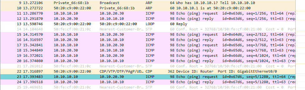
Switch#Now see below, I ping between VLAN's from Alice to Sam. From 10.10.10.10/24 to 10.10.20.30/24. I have cleared ARP on the host and cleared the MAC address table on the switch. The below Wireshark was taken on both the Gi3/0 (for VLAN10) and on GI3/1 (for VLAN20)
VLAN10:
VLAN 20:
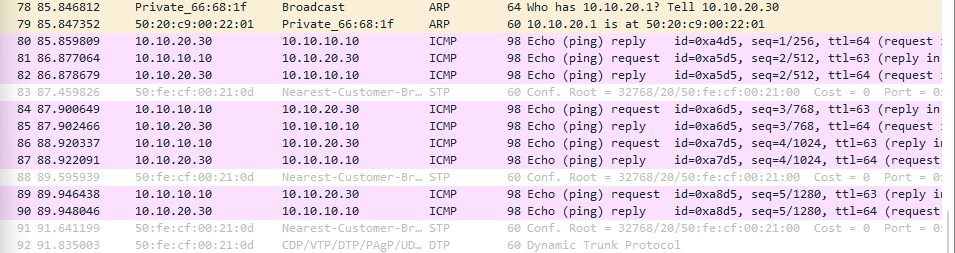
We can see that basically what happens is R1 had flooded the broadcast to the end host and since Wireshark is only checking the Gi3/1 interface we only see the ARP broadcast initiated by Sam.
Alice> ping 10.10.20.30

84 bytes from 10.10.20.30 icmp_seq=1 ttl=63 time=6.149 ms
84 bytes from 10.10.20.30 icmp_seq=2 ttl=63 time=3.999 ms
84 bytes from 10.10.20.30 icmp_seq=3 ttl=63 time=3.509 ms
84 bytes from 10.10.20.30 icmp_seq=4 ttl=63 time=3.381 ms
84 bytes from 10.10.20.30 icmp_seq=5 ttl=63 time=4.796 ms

Alice> sh ip

NAME        : VPCS[1]
IP/MASK     : 10.10.10.10/24
GATEWAY     : 10.10.10.1
DNS         :
MAC         : 00:50:79:66:68:1b
LPORT       : 20000
RHOST:PORT  : 127.0.0.1:30000
MTU         : 1500
This is actually discussed in further 2.2 Configure and verify interswitch connectivity - In here we go into the concept of Router on a Stick.
Comments