The problem with Spanning-Tree
Spanning-tree solves a specific problem - Loops. It does this by blocking redundant links. Link's which it believe is not critical for communication it puts them in blocking state. This blocks all fording of data traffic on this link.
This causes an issue when it comes to redundancy. What do we mean? Suppose the below diagram:
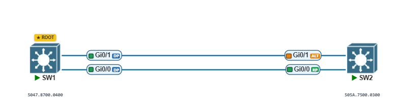
In this scenario the network engineer wanted to add more throughput and capability to their network due to an increase in utilization. So they have added a new uplink to this switch. However, this will absolutely create a loop if all 4 ports are forwarding at the same time, an ARP from one port will be received and forwarded out the other. So STP blocks this as you can see.
This happens no matter how many links we add you can see below vie added 2 extra links as per spanning-tree all of these are blocked:
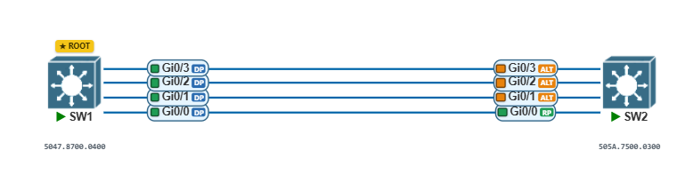
This is a problem. If our network grows larger and more severs or endpoints which are generating more bandwidth is required, spanning-tree is a major obstacle. If we have just this one link active and a server on the other end, and its only a 1gig link? Well that is going to throttle the connection. This is known as oversubscription.
It also wastes the capability of the other links. Rather than having 4gig of capacity we only have 1 Gig.
What can we do to solve this issue? EtherChannel is the solution.
Etherchannels
Etherchannel is a way to bundle multiple physical ports (the actual cables we are plugging into switchports) into a single logical virtual link. You can see this below:
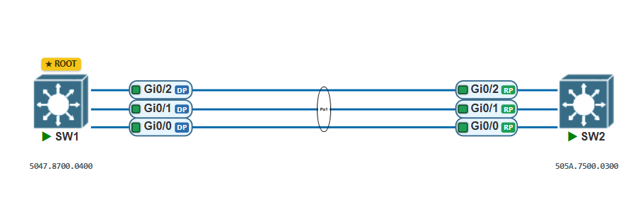
Here we have multiple physical links from Gi0/0 - Gi0/2 between both these switches. As we saw before, typically STP would block these 3 other links. However, with Etherchannels we bundle these extra 3 links/ports into a single virtual link. This is known as Etherchannel, Portchannel, Link Aggregation, or even channel group, there are multiple names for this technology and they all achieve the same thing.
Because it only sees one link, if an ARP message comes in, it wont loop around.
Characteristics of Etherchannels
We can bundle up to 16 ports in an Etherchannel. However, we can only have 8 links which are actively forwarding data traffic. The other 8 links are known as "hot standby". If any of the primary link fails, one of the other links takes over.
Even if we do bundle 16 links into 1 Etherchannel, STP will still see this whole bundle as just 1 virtual link.
Etherchannels also aggregate the bandwidth. Meaning instead of having just the 1gig of bandwidth, we can have traffic flows that underneath go through each of the links, yet STP only sees 1 link. This means we can have 4gig bandwidth. If I had 8 active links that would be 8gigs of bandwidth over 1 virtual Portchannel.
Etherchannels also provide many benefits such as:
- Load Balancing
- Increased Bandwidth
- Less STP conflicts.
PAgP & LACP
Etherchannel has two protocols. PAgP is Port Aggregation Control Protocol. PAGP is Cisco Proprietary. This protocol is not as common as LACP. Etherchannel technology itself was developed by Cisco.
LACP which is Link Aggregation Control Protocol. This is an open standard that any vendor can implement on their switches. For example, if we have an FortiSwitch connected to a Cisco switch, we would have to run LACP. PAgP would not work.
These two protocols are basically algorithms used to setup, manage and maintain the Etherchannel.
Etherchannel Requirements
Etherchannels do have requirements that must be met between two switches that want to form an Etherchannel.
| 1)Same port speed | We cannot have ports of varying speed in an Etherchannel. E.g. FE0/1 & Gi0/0 would not work. | Only use same port speed. FE0/0 & FE0/1 would work. Gi0/0 & Gi0/1 would work |
| 2)Same Duplex | We cannot have a mix of half duplex or full duplex. | Always use Full-Duplex. |
| 3)Same port type | We cannot have one side as trunk and the other side as access | 99% of the time between switches set it as trunk. |
No matching rows.
LACP is actually what checks all this and ensures that both sides are compatible.
Once an Etherchannel is formed, in cisco terms its called Port-Channel on the switches. Typically called PO1 or PO2. These are exactly the same in the software as any other type of link.
Tip
Once a Port-Channel is formed make sure all future changes are made on this Portchannel. So for example if we need to allow VLANs over this Portchannel, make the change on here.
LACP Configuration
| Active | Actively sends LACP Control Messages. Handles the negotiation. | One side must be configured as active. In practice most engineers set both sides as active |
| Passive | Actively listens for LACP Control Messages Does not send LACP Messages | One side must be set to passive. Can never have both sides passive. |
| On | No dynamic building of Etherchannel. Basically a static Etherchannel. | Both sides must be configured as on mode. Useful for Portchannels with servers. This is possible since they have multiple NICs. But SRV doesnt understand LACP control plane messages thats why we use on mode. |
No matching rows.
SW1 Configuration:
SW1#conf t
SW1(config)#int range gi0/0 - 3
SW1(config-if-range)#channel-group 1 mode active
Creating a port-channel interface Port-channel 1

*Jul 22 19:30:19.442: %LINEPROTO-5-UPDOWN: Line protocol on Interface GigabitEthernet0/0, changed state to down
*Jul 22 19:30:19.448: %LINEPROTO-5-UPDOWN: Line protocol on Interface GigabitEthernet0/1, changed state to down
*Jul 22 19:30:19.453: %LINEPROTO-5-UPDOWN: Line protocol on Interface GigabitEthernet0/2, changed state to down
*Jul 22 19:30:19.459: %LINEPROTO-5-UPDOWN: Line protocol on Interface GigabitEthernet0/3, changed state to downs

SW1(config-if-range)#int po1
SW1(config-if)#switchport trunk encapsulation dot1q
SW1(config-if)#switchport mode trunk
SW1(config-if)#end

*Jul 22 19:30:26.995: %LINEPROTO-5-UPDOWN: Line protocol on Interface GigabitEthernet0/0, changed state to up
*Jul 22 19:30:26.997: %LINEPROTO-5-UPDOWN: Line protocol on Interface GigabitEthernet0/1, changed state to up
*Jul 22 19:30:26.999: %LINEPROTO-5-UPDOWN: Line protocol on Interface GigabitEthernet0/2, changed state to up
*Jul 22 19:30:27.003: %LINEPROTO-5-UPDOWN: Line protocol on Interface GigabitEthernet0/3, changed state to up

*Jul 22 19:30:37.974: %EC-5-L3DONTBNDL2: Gi0/0 suspended: LACP currently not enabled on the remote port.
*Jul 22 19:30:38.106: %EC-5-L3DONTBNDL2: Gi0/3 suspended: LACP currently not enabled on the remote port.
*Jul 22 19:30:38.236: %EC-5-L3DONTBNDL2: Gi0/2 suspended: LACP currently not enabled on the remote port.
*Jul 22 19:30:38.564: %EC-5-L3DONTBNDL2: Gi0/1 suspended: LACP currently not enabled on the remote port.
*Jul 22 19:30:38.985: %LINEPROTO-5-UPDOWN: Line protocol on Interface GigabitEthernet0/0, changed state to down

*Jul 22 19:30:39.110: %LINEPROTO-5-UPDOWN: Line protocol on Interface GigabitEthernet0/3, changed state to down
*Jul 22 19:30:39.250: %LINEPROTO-5-UPDOWN: Line protocol on Interface GigabitEthernet0/2, changed state to down
*Jul 22 19:30:39.564: %LINEPROTO-5-UPDOWN: Line protocol on Interface GigabitEthernet0/1, changed state to down

SW1#show etherchannel summary
Flags:  D - down        P - bundled in port-channel
        I - stand-alone s - suspended
        H - Hot-standby (LACP only)
        R - Layer3      S - Layer2
        U - in use      N - not in use, no aggregation
        f - failed to allocate aggregator

        M - not in use, minimum links not met
        m - not in use, port not aggregated due to minimum links not met
        u - unsuitable for bundling
        w - waiting to be aggregated
        d - default port

        A - formed by Auto LAG


Number of channel-groups in use: 1
Number of aggregators:           1

Group  Port-channel  Protocol    Ports
------+-------------+-----------+-----------------------------------------------
**1      Po1(SD)         LACP      Gi0/0(s)    Gi0/1(s)    Gi0/2(s)
                                 Gi0/3(s)**       -> Notice we have bundled all these 4 into an Etherchannel but currently only 1 side is configured so its all in suspended state.
SW2 Configuration:
SW2(config)#int range gi0/0 - 3
SW2(config-if-range)#channel-group 1 mode active
Creating a port-channel interface Port-channel 1

SW2(config-if-range)#exit
SW2(config)#int po1
SW2(config-if)#switchport mode trunk
SW2(config-if)#switchport trunk encapsulation dot1q
SW2(config-if)#switchport mode trunk
SW2(config-if)#exit

*Jul 22 20:10:18.386: %LINK-3-UPDOWN: Interface Port-channel1, changed state to up
*Jul 22 20:10:19.388: %LINEPROTO-5-UPDOWN: Line protocol on Interface Port-channel1,
Verification on both sides:
SW1 Verification:
SW1#show etherchannel summary
Flags:  D - down        P - bundled in port-channel
        I - stand-alone s - suspended
        H - Hot-standby (LACP only)
        R - Layer3      S - Layer2
        U - in use      N - not in use, no aggregation
        f - failed to allocate aggregator

        M - not in use, minimum links not met
        m - not in use, port not aggregated due to minimum links not met
        u - unsuitable for bundling
        w - waiting to be aggregated
        d - default port

        A - formed by Auto LAG


Number of channel-groups in use: 1
Number of aggregators:           1

Group  Port-channel  Protocol    Ports
------+-------------+-----------+-----------------------------------------------
1      Po1(SU)         LACP      Gi0/0(P)    Gi0/1(P)    Gi0/2(P)
                                 Gi0/3(P)

SW1#
SW2 Verification:
SW2#sh etherchannel summary
Flags:  D - down        P - bundled in port-channel
        I - stand-alone s - suspended
        H - Hot-standby (LACP only)
        R - Layer3      S - Layer2
        U - in use      N - not in use, no aggregation
        f - failed to allocate aggregator

        M - not in use, minimum links not met
        m - not in use, port not aggregated due to minimum links not met
        u - unsuitable for bundling
        w - waiting to be aggregated
        d - default port

        A - formed by Auto LAG


Number of channel-groups in use: 1
Number of aggregators:           1

Group  Port-channel  Protocol    Ports
------+-------------+-----------+-----------------------------------------------
1      Po1(SU)         LACP      Gi0/0(P)    Gi0/1(P)    Gi0/2(P)
                                 Gi0/3(P)
STP Interaction with Multiple Etherchannels
I have now bundled Gi0/0 - Gi0/2 into PO1 ports and gi0/3 & gi1/0 into PO2. Spanning-Tree sees this as two separate Links. Meaning instead of getting 5gig of bandwidth, we only get 3 gig from PO1. Since STP will block the traffic from PO2 as seen below:
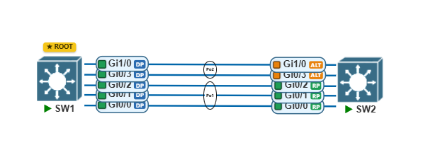
As you can see, we have a new portchannel 2 between these two switches. However, STP will block the 2nd link. Why? Because STP considers this a new interface and thus it has to go through STP Tiebreakers mainly:
- Switch Priority
- MAC Address Preference
- Port Priority.
PO1 wins out and goes in forwarding state. PO2 however will go in alternate state. To be honest with RSTP it will only take about 6 seconds to go to forwarding state for PO2 but we may not want this.
This specific issue can be resolved in two ways.
- Remove Layer 2 Entirely and use a Layer 3 Routed Network (This is outside of this blog scope).
- Use Nexus Switches and use a technology known as VPC (This is outside of this blog scope).
Layer 2 vs Layer 3 Etherchannels
A Layer 2 link is one that has zero care for Layer 3 or IP addressing. For example when forwarding layer 2 frames a L2 switch has zero regards for IP addressing. It only cares about forwarding frames based on destination MAC addresses and populating its CAM table. Anything that forwards based on L2 frames then they will be L2 links.
A Layer 3 link is a link that cares about Layer 3 and IP Addressing. Routers for example have interfaces connected to a switch, which does have a MAC on its interface, but for forwarding information it uses a combination of L3 and L2. It cares about packets and Layer 3 information. Endpoints are also L3 links.
Standard Etherchannels are bundling Layer 2 links between switches. It only understands L2 frames. This has been demonstrated multiple times above.
But we can configure two or more links between routers and get a L3 Etherchannel. We configure it the same as a standard Etherchannel however we go inside the PO[x] and assign an IP Address to this interface. This makes it a Layer 3 Etherchannel.
Comments